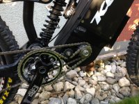
LightningRods mid drive kit

LightningRods said:
I think that torque makes everything happen, both good and bad. Take torque out of the equation for horsepower, watts or work and what's left?

I agree that torque breaks inadequate driveline parts. Without exception I say make the driveline better.

You cannot take torque out of the equasion. What you want to do is reduce torque while increasing driveline component speed, the reduce the drive line speed at the final drive at the rear wheel. This will dastically reduce the abusing load on the rear cogs, chain, and frame.

Again, torque is static pressure. If you push against a wall, you are applying torque, while no useable work is being done. Now, push against a car in neutral with the same force (same torque) and the car starts to roll. That movement multiplied by the pressure is measured in watts. A bicycle chain on the pedal side has a low surface speed. That means that to put a certain amount of wattage to the rear wheel will put a relatively high amount of torque on the chain and rear cog to move the bike due to that low chain surface speed.

The key to making light weight components survive is increasing surface speed for a given power output. When surface speed of a component increases (keeping the wattage constant), the torque loading (static pressure) drops. For instance, pushing 3,000 watts through a system geared for 30mph using the largest 34 tooth cog, the chain and sprockets will see a specific torque loading. Now, run the same 3,000 watts at 30mph through a system running a 16 tooth rear cog (making up the gearing difference at the motor pulley) the torque loading on the chain and rear cog will double. This is the benefit to running relatively tall gearing at the drive system and using a very large cog at the rear wheel. The chain speed goes way up and the torque loading on the chain and rear cog drops significantly. In that instance, the torque load is still the same at the wheel, but the chain and rear cog is trading torque for surface speed.

I did not mean to clog up the thread. I was just trying to shed some light on why that suspension link cracked.

Game on! :D

Matt
 
I absolutely agree about keeping torque multiplication down until the last stage. We've been talking about this recently on this thread. Trying to slow the motor speed down enough to match human pedaling speeds at the bottom bracket is not realistic with a high torque motor.

When someone's swing arm or chain stays get bent, or a rear suspension component blows up, that is final stage stress. The frame just wasn't up to the driving forces at the rear wheel. I think that one of your 3220 Astro drives would do every bit as good a job of blowing up a weak frame. You may be running 10,000 rpm instead of 3,000, but you also typically use a lot more reduction to end up with similar wheel speeds. What's avoided in static torque gets made up for by torque multiplication, I betcha.

This is a really interesting topic. I'd love to have a chassis dyno for about a week to get some hard numbers on this.

Always fun shooting the shit with you, Matt. :D
 
Yup, it's all a matter of where the torque is concentrated. A high chain speed with a huge rear sprocket concentrates the torque at the hub and takes it away from the driveline. Of course higher component speed increases fictional wear. It is a tradeoff.

I love discussing this stuff.
 
I've been working on a "unified motor theory" (* I know that sounds arrogant), but....I stumbled across a motor theory term "Tangential Magnet Speed", which I assume was used to clarify that when many people are talking about "motor speed" many will instantly assume you are talking about RPMs. Using RPM's does not take into account a small diameter motor (of the same stator width), and a large diameter motor. The larger diameter motor uses a much faster magnet speed (only talking about direct drive motors so far here). Tangential Magnet Speed (TMS) instantly clears that up, when comparing two motors of different diameters

The Bafang BBSHD and BBS02 both use the same motor lamination, so...precisely the same motor diameter / TMS. The BBSHD makes more torque than the BBS02 when they are both fed the same watts, because the BBSHD has 30% more "Swept Magnetic Area" (SMA?). Also LR small-block compared to the LR big-block, at the same input watts.

Which brings us to a final new term...how to differentiate between a single-speed non-hub, and the bottom-gear/top-gear of a mid drive that has the use of the bikes gears? The rough version I have now is "SMA X TMS per meter traveled" (which takes into account the tire OD and gearing between motor and distance traveled)

Here's a useful hint to the younger ES members, when my wife catches me staring into space (*drooling slightly) and asks what I'm thinking about? I say "remember when we first met, I knew right away that I wanted to get to know you better, and today...I can't believe how lucky I am"

It goes over MUCH better than "I've been working on a unified motor theory (I know that sounds arrogant)..."
 
spinningmagnets said:
...when my wife catches me staring into space (*drooling slightly) and asks what I'm thinking about? I say "remember when we first met, I knew right away that I wanted to get to know you better, and today...I can't believe how lucky I am"
you made my day! and the strangest thing about it: THEY BELIEVE YOU! :)
 
My wife has a "real" job that involves pouring over volumes of records and transcripts. She tells me her stories of digging through records and finding infractions and I tell her about how I figured out how to attach a widget to a frammistat. We can't tell these stories to anyone else so we listen to each other. It's our arrangement.

Gearing is really interesting. I alternate between thinking of gearing as leverage and thinking of gearing as expanding and contracting timelines. It's probably both simultaneously. When you're in a low gear you are pulling on a longer lever. Like a long breaker bar the gear rotates more slowly at the center for every unit it travels at it's circumference. By doing this it's magically compressing energy from the edge to the center. When you take a high rpm/relatively low torque motor and run it through a reduction system the extra units of motion (rpm) are compressed by the reduction into more twisting force in fewer units. It's making that little high rpm motor more like a big torque motor. We've seen this in cars and motorcycle for over 100 years.

The range of motors in electric bikes, from tiny RC motors to ginormous 25 lb hub motors, has become pretty huge. One of the most interesting tests that could be done would be to put these various configurations onto a chassis dyno and measure energy in and power out. The little RC motors tend to be more efficient than big hub motors, but then they have the power losses from all of those stages of reduction. I'd like to see how it all comes out.
 
To expand on what matt is saying I always think of gearing the following way:
For any given power, how many chain links or gear teeth per second are you using? If you are using many links per second, then the force on any link is low. If you are using few links per second then the pulling force is high. So if you have a huge rear sprocket and you were to measure the tension on the chain it would be relatively low just many times per second. If you have a small rear sprocket then the stress on the chain is very high but only a few times per second.

You are basically choosing where you want the massive lever to occur. With a low speed chain at high power you pass all the stress to the frame. With a high chain speed large ratio reduction like matts bikes the big lever is from the sprocket to the hub. If you were to put a strain gauge on the chainstays of these bikes Matt's would measure way less stress per given power than a BB mid-drive with small cogs. The BB mid-drives are usually running the final reduction in overdrive which is maximum chain tension and stress. Saving the large reduction for last passes the torque through last part and strongest part of the system. Hence the 20kw bike chain.
 
DanGT86 said:
The BB mid-drives are usually running the final reduction in overdrive which is maximum chain tension and stress.

Having high levels of reduction meet overdrive is a design error. I'm realizing that more and more. It's very much like the irresistible force meeting an immovable object.

The main question I ask customers now is "Do you want to be able to pedal with the motor?" Fortunately the high power users tend to not care about pedaling. I'm using far less reduction and correspondingly less overdrive on my high power drives.
 
yeah, the normal cadence systems are all going to be plagued by the high stress load problem when the rear chain speed is human bike speed. If the rear sprocket is 4x larger then you can run 4x human power with only normal human chain/frame load. Problem is you need 4x the pedal cadence at that point.

A good solution might be to get a human cadence overdrive done near the bottom bracket. So use an IGH near the bottom bracket to get the chain speed up at a given cadence and use giant 60-80tooth rear sprockets. Problem there is you are passing the leverage to the rear freewheel or cassette pawls. That's why the LH drive sprockt mount is so useful for high power.

I wouldn't call the overdrive in the current system a design error. Its just a compromise to get other desireable factors like normal pedal cadence and the native engineering of existing bike components. Its not like all these frame failures are common yet. The 7500watt BB drive i saw yesterday might be a different story.
 
Sadly my intention was to go to a much larger rear sprocket. I even have had the adapter and 38t ready to go for quite a while. I was waiting on someone in the United States to respond to emails to purchase the larger 18t 3/4" sprockets..... and in the mean time upped to the 40t bicycle chain sprocket for more engagement and avoidance of the 219 nuts.

Unfortunately these parts are not easy to get anywhere else in the world that I can find anyway.
Mike doesn't respond to my emails either.

Please share a link if any Aussies have some or link to local suppliers that fit the LR rod specifics. or even international suppliers that you buy from.

The last website I spotted in the states wants $50 bucks to ship a $10 sprocket.... or $80 au all up. yay for cheap replacements.

Feel a bit cornered into a niche market here.

Just to share more info on the failed part since it seems fair to the discussion. The complexity of how suspension works most probably plays a large factor too. A lot of people talk about how they ride various frames with various motors etc, but the terrain is hard thing to share and it makes a huge difference to validate claims of what system works better.

I could probably run a geared mac motor off road too over massive obstacles. Yet try doing that continually up hill with extremely rough terrain those gears might not last too long.

I have not seen any info since there are so many suspension types, about how loading the chain during different cycles of suspension travel. I can only guess that my beefy m6 is awesome at taking massive downhill drops, but not taking almost full compression while power is pulling to one side too. lol.

And yes we have almost full compression while pulling max power because the terrain demands it uphill. If it didn't I could get a 12t mac.

The last point is hypothetically speaking if I had installed the 38t rear or even an lmx 60t and this link broke, would the conversation be different enough to justify repairing one link (assuming the whole top end isnt already warped beyond repair). The same 3.5kw would still be at least running half it's potential in my opinion.

My dream is to have access to around 5kw which is the magical number producing the magical torque figure which produces zero bogging on extreme terrain. You can argue about terms but they are the ones I have experienced that I would like to replicate in non fail situation. And I know this motor and motor brackets can do it. The bicycle suspension / LR stock components / JS system in the version that I received half a year ago aren't capable of it for much longer than 20ah.

Dream on. :lol:
 
LightningRods said:
DanGT86 said:
The BB mid-drives are usually running the final reduction in overdrive which is maximum chain tension and stress.

Having high levels of reduction meet overdrive is a design error. I'm realizing that more and more. It's very much like the irresistible force meeting an immovable object.

The main question I ask customers now is "Do you want to be able to pedal with the motor?" Fortunately the high power users tend to not care about pedaling. I'm using far less reduction and correspondingly less overdrive on my high power drives.
that's why i chose this setup, which imho gives you the most possibilities to adapt your pedalling cadence to the bike speed. you can choose the gear count of the freewheel, the big gear at the cranks and the gear driving the rear wheel until it matches. this allows me to pedal along at 65km/h top speed (40mph).
and there is a relatively small, high rpm gear that drives the rear wheel. which means lower stress on the chain.

2014-08-17 at 18.21.19.JPG
 
That's the design that Crossbreak likes to call the "Crossbreak Arrangement." I've looked at that layout for some time. Here's what I don't like about it:

crossbreakarc.jpg


The red circle is the swingarm pivot point and the red dotted arc is the path that the rear axle/hub take during suspension motion. The blue circle is the final drive sprocket in the Crossbreak Arrangement and the dotted blue arc is the path that the final drive chain wants to take. You can see that during suspension compression or drop that the arcs don't line up. This causes the chain tension to fluctuate during suspension movement. Add to that a long, heavy, floppy drive chain and you have a final drive that wants to come off of the sprockets. I've considered adding chain guides and spring tensioners to try to compensate for the geometry problem. It gets more and more complicated trying to band aid an inherent problem.

The proper place to put the final drive sprocket is right on that red circle. That's where Motoped cleverly puts it. On your typical downhill pedal bike the manufacturer has already moved the chainwheel back too close to that pivot. That's because they're trying to approximate the drive chain with the swingarm pivot to minimize the problem that I've shown above. It leaves no room to add a motor drive sprocket where we really want it.

The bike that most people want to put an electric motor on is the downhill bike. It seems like a good idea. Plush ride, sturdy construction, miserable to pedal. Unfortunately they are also the hardest bikes to fit a motor to. Hub motors ruin the rear suspension and trying to fit all of the pieces of a mid drive ends up being one kind of compromise or another.

Personally I think the Crossbreak Arrangement is best for street bikes. Chain management is a serious issue off road. The weight of the chain really gets it flopping around in the rough stuff. Longer is worse. Fluctuating chain tension is worse. If I were going to build a Crossbreak drive I'd put it on a hard tail.
 
What are y'all's completed big block builds generally weighing?

I put mine on the scale last night and was surprised to find it at around 73lbs with no racks or anything. Just the bike, the big block, a waterproof enclosure I built, an admittedly large 52v battery, and a 60v-12v transformer for a couple off road lights.
 
I picked up some more parts from the laser cutter today including the new #219 drive sprockets for the Qulbix Q76 and Q140.

Qulbix219Drive.jpg


The final drive is 1:1 which is basically like being in low gear on a pump bike. Motor reduction is 7.4:1 overall. This creates the same rear wheel ratio as 30:1 motor reduction running through 4:1 overdrive to the rear wheel. Torque at the BB freewheel is 1/4 as much with the new gearing and load resistance to the rear wheel is 1/4 as much. I don't know that this will mean 1/16 the strain on the BB freewheel and drive components, but clearly it is going to be a lot less than before.

I'm using 18t driver sprockets on both the motor and jackshaft secondary, all of the large sprockets are .130" stainless steel, and the drive chain is D.I.D. #219 all the way from the motor to the rear wheel. All ready for the 5000+ watts that Mammalian plans to run through it on his Q140.

The six bolt disc brake flange for the rear wheel sprocket will be on the right side. The disc brake rotor will be in it's stock location on the left.
 
More magic, I want the one on the left. should have put a banana in there for scale but it's probably equivalent to a 36t bicycle sprocket off the top of my head.

Can someone ask him the price and availability? OR should I PM someone to PM him and then get them to PM me back?

They look strong and will last a long time but would prefer iso to 219 hole adapter to be able to dial the gearing and last a life time if the holes dont stretch, post sale. Guessing though this steel is much stronger than the stock "normal" steel adapters.

This is what $80au gets you... not sure if I should let the stupidity begin and blame it on second hand fatigue.... or be patient for the US parts.

13995408_10154265872209845_1106869062873742806_o.jpg
 
John Bozi said:
More magic, I want the one on the left. should have put a banana in there for scale but it's probably equivalent to a 36t bicycle sprocket off the top of my head.

Can someone ask him the price and availability? OR should I PM someone to PM him and then get them to PM me back?

They look strong and will last a long time but would prefer iso to 219 hole adapter to be able to dial the gearing and last a life time if the holes dont stretch, post sale. Guessing though this steel is much stronger than the stock "normal" steel adapters.

This is what $80au gets you... not sure if I should let the stupidity begin and blame it on second hand fatigue.... or be patient for the US parts.

13995408_10154265872209845_1106869062873742806_o.jpg

Check that out!!! John found a TIG welder to fix his broken part!!! While your at it...reinforce that baby with lots more metal.
 
LightningRods said:
I picked up some more parts from the laser cutter today including the new #219 drive sprockets for the Qulbix Q76 and Q140.

Qulbix219Drive.jpg


The final drive is 1:1 which is basically like being in low gear on a pump bike. Motor reduction is 7.4:1 overall. This creates the same rear wheel ratio as 30:1 motor reduction running through 4:1 overdrive to the rear wheel. Torque at the BB freewheel is 1/4 as much with the new gearing and load resistance to the rear wheel is 1/4 as much. I don't know that this will mean 1/16 the strain on the BB freewheel and drive components, but clearly it is going to be a lot less than before.

I'm using 18t driver sprockets on both the motor and jackshaft secondary, all of the large sprockets are .130" stainless steel, and the drive chain is D.I.D. #219 all the way from the motor to the rear wheel. All ready for the 5000+ watts that Mammalian plans to run through it on his Q140.

The six bolt disc brake flange for the rear wheel sprocket will be on the right side. The disc brake rotor will be in it's stock location on the left.


If these sprockets are made like the 40 tooth sprocket I already have, well these will be rock solid and wear really well. I can't wait to get the ones I just ordered!
 
The LighningRods website states that the 3000w big block should be run "with a high power capacity derailleur". What make and model would that be?
 
Am looking at a 2011 Norco Bushpilot
https://www.norco.com/bike-archives/2011/bushpilot/

Has FSA BB-7420ST Cartridge, is this BB shell likly to be suitable ?
 
sather, that would be something like a SRAM X9 or so...
We use SRAM X9, X0, Shimano XT and they all do a good job on the Smallblock.

got my new parts; upgraded Jackshafts, new adapters for the big belt-pully, some sprokets and small stuff...
had them laying around for some days, Installed it all today.


other side:


New 15mm jackshaft in alu housing VS old dirty first-badge Jackshaft


Very happy with the new parts, look much higher grade and much easyer to replace sproket and beltpully-adapter now. Also 15mm axle (instead of 12mm - old axle) makes a big difference, and i would love to try 3500-4000W, but controller restrict to about 3200 max. (Lyen 12 fet at 75V)
Now have to finish the bike, cant wait to ride it again

will probably weld the jackshaft in place with 1 or 2 weld-dots per side, as im not planing to change anything on the reduction in future.
more fotos and stuff about the parts in my tread soon.

Cheers guys
 
Back
Top