Mars Electric LLC Axial Flux Motor

johnrobholmes said:
I haven't heard anything from Mars addressing the motor noise lately, but I haven't pushed the issue too hard. If you wanted to pick one up for yourself, contacting them would get you a motor pretty fast I imagine.

As-is, I have no doubt it could make an awesome ebike motor for 1hp average use. Run it through the derailleur and it would make a pretty potent setup.

is the noise from the motor or incorrect controller ?


John at Marselectric wants to know ....

"I am still waiting on feedback to see if the motor is a good choice.

Are there any changes that need to be made at this time? "
 
John writes ......


"I need the voltage, maximum speed, maximum voltage , maximum and continuous current, any size or length requirements, the shaft size, the type of terminals, ect.

This will be a special motor just for this market.

John Fiorenza "
 
Hi Folks, :mrgreen:

OK, I have finally got our first "mini E Tek" installed on a nicely modified Rans Stratus. I prefer this motor to be used
as a Mid Drive, and had requested this motor to be mounted up to a Cyclone gear box with a hardened, double
clutch out-put shaft. Here are a couple of Photo's of this set up. I am working to have this narrow version made up,
without holes to keep the dirt out. I also like the Wires coming out of the side, like this.
What would you prefer, if you could have this in your favorite configuration?...

Josh K.
 

Attachments

  • Axial 1.JPG
    Axial 1.JPG
    233.3 KB · Views: 1,977
Here is a nice side view of this set up.
I use a fixed cog on the final drive, and a large free wheel on the pedal input of the mid drive system.
I have coupled the motor up to a Castle Creations speed controller, and a set of A123 Lithium ion Batts,
24 volts, and 21 amp hours of go go juice. I am expecting about 30-32 Mph at about 13-14 watt hours per mile.
I guess I will have to hook the controller up to a PC, and see what the amp max setting is at...

Hoping to get the wiring up and going in the next couple of days. Need to get the fuel meter inline, switched,
and see if I can get into and possibly adjust the controller. A new wind shield wouldn't be a bad idea with
these Cold Colorado winds...

Peace, Josh K.
 
That should be a real good setup Josh, if you are using a Castle HV controller, it might be cool to have a series/ parallel switch to get some serious speed out of that motor. 8) Let us know how show screams. Will you be selling these new revamped motors?
 
I like the battery frame work.

How many teeth on the pedal crank ?

Kv of motor ?
 
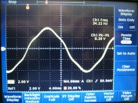
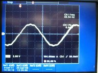
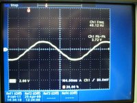
Here are some waveforms for the Axial Motor and a large and medium Turnigy outrunner. First our Axial friend: These measurements were taken with the lathe motoring the motor at approximately 400 rpm. All are open circuit readings on one phase.
RPM: 400 8.28 Volts Peak to Peak 34.22 Hz
AxialWave1.jpg

Note that the wave shape is "peaky", this is not likely the best wind for trapezoidal excitation. One might think that this motor would "like" a modified sine wave drive. That may well "quiet things down" a bit.

Now the Turnigy C80100-130
RPM: 400 6.04 Volts Peak to Peak 40.54 Hz (different due to motor pole count)
C80100-1301.jpg

Note that this guy has the flat top and a more continuous slope. Definitely should like trapezoidal drive better.

Finally the medium Turnigy some are using on direct rear wheel drive the C6374-200
RPM: 400 3.72 Volts Peak to Peak and 40.12 Hz (same pole count as the C80100-130)
C6374-2001.jpg

Again, a reasonable flat top, and a nice slope to the waveform. Should be happy with a trapezoidal drive.
 
No I considered it very quiet when being motored by the lathe. I had modeled the rotor in Solidworks, and wanted to do a FEA on it to see how it deflected under load to see if it was the "speaker". To make a long story short, the authorization key dongle is not being recognized by my desktop, and I somehow erased the solid model I built of the rotor... somedays nothing goes right! :x
 
Guys, keep in mind the scope traces above are back EMF traces. The motor was being driven by my lathe at 400 RPM. It was not loaded. It was quiet. I don't think we can draw much info with respect to the noise from this test, unless I am missing something.
 
The noise from the previous test likely came from being driven from standard 6 step commutation. I was just wondering if the motor vibrated loudly while spinning no load and no power.
 
Josh K. said:
Hi Folks, :mrgreen:

OK, I have finally got our first "mini E Tek" installed on a nicely modified Rans Stratus. I prefer this motor to be used
as a Mid Drive, and had requested this motor to be mounted up to a Cyclone gear box with a hardened, double
clutch out-put shaft. Here are a couple of Photo's of this set up. I am working to have this narrow version made up,
without holes to keep the dirt out. I also like the Wires coming out of the side, like this.
What would you prefer, if you could have this in your favorite configuration?...

Josh K.


Nice motor. I see it's serial number 1. Bound to be a collector's item :wink:

That looks slightly bigger than my BMC 600w scooter motor. BTW, the BMC motor is quite noisy at high load too. It really 'sings' when you hit the sweet spot in rpm. I'm sure it's the rotor ringing. I'm not sure if there's an easy way to quiet such things. Making the rotor thicker would be one way, but that adds unnecessary weight. Maybe laminate a layer of fiberglass over it or something might dampen the ringing.
 
John at Marselectric is aware of the noise issue, so one would think that the next generation motor will address that ?

and I'm sure Josh will be tweaking it also.

good to see interest in new motors that could be affordable and efficient.
 
I'm sure the noise would be less using a sinusoidal drive with almost any motor. Even a real trapezoidal drive would be quieter than the typical 6 step square wave drive. I think one of the trade-offs other than complexity is the output would need to be constantly swtiching at high frequency to create the waveform, so switching losses in the FETs would be greater under some conditions. This loss might be more than made up for by improving the efficiency of the motor, but you still have some extra heat to deal with in the controller.

There are very few controllers that offer a sinusoidal or trapezoidal output.

I think all the hardware needed is there in a typical controller, just a change to the software may be all that's needed if the processor is fast enough and has enough memory.
 
Fechter is spot on with respect to switching losses. I am working on coding up a switching loss model next month and will share some results when it is finished. But here is the trend: As we go up in current we parallel FETs or go with Hybrid Module FETs, (or go to very high voltage > 150 Volts and use IGBT modules) the result is a significant rise in FET gate capacitance and required charge movement for switching on the gate.

For example Qty (1) IRFB4110 = 150 nCoulombs, Qty(3) IRFP4468 = 1080 nC, and the big VMM1500-0075T2 = 1950 nC. This larger gate capacitance slows the switching of the active element (FET) and puts us in the linear region (higher Rds On) longer. These factors plus supplying and dumping to ground the gate charge add up to the "switching loss". It is frequency dependent. This implies that you can do more "fancy" waveform shaping with the little FETs; but when your controller gets the steroid treatment, you are headed towards a slower PWM frequency and a simpler algorithm.
 
as far as i can tell all the solar racers use sine drive.
so there's must be a net eff gain.

in fact every other industry that uses BL motors has almost completely ported over to sinusoidal controllers (or is planning to just waiting for the existing equipment to die) despite the fact they're more expensive.
why do u suppose that is?
 
Toorbough ULL-Zeveigh said:
as far as i can tell all the solar racers use sine drive.
so there's must be a net eff gain.

in fact every other industry that uses BL motors has almost completely ported over to sinusoidal controllers (or is planning to just waiting for the existing equipment to die) despite the fact they're more expensive.
why do u suppose that is?

I'd guess that sine drive in industrial motors is primarily for lower torque ripple, better torque control for things like servo applications and maybe better power factor correction for high power stuff. The efficiency difference is small, enough for the solar guys to want to take advantage of it to squeeze the last tenth of a percent out of their systems but probably only a tiny practical difference over the full working range of an ordinary ebike motor.

There's also little need for sine drive if the motor is a radial, non-skewed, design with rectangular slots and magnets, because a trapezoidal waveform will be a closer match to the motor's BEMF. Axial flux motors that use odd shaped magnets, like this one with it's rounded magnets, will have a different BEMF waveform, as Bigmoose has shown, and so may be better suited to a different shape of drive waveform. If this motor had magnets that were shaped as sectors of a circle, like the Lynch design, then my guess is that it would also like trapezoidal drive. Maybe it uses these odd shaped magnets to get around Cedric's patents?

Jeremy
 
The efficiency difference is small, enough for the solar guys to want to take advantage of it to squeeze the last tenth of a percent out of their systems but probably only a tiny practical difference over the full working range of an ordinary ebike motor.
Have you any idea, how much is the difference (in %).
I also read that a Space Vector PWM motor control had ~15% more tension than a traditional sine wave motor control. Does that mean that the power, and effectiveness is also upgraded by 15%?
 
If you look at motor losses and efficiency then a really good motor can be around 90 to 94% efficient when running with trapezoidal drive. My guess is that sine drive might possibly give a gain of between 0.1% to perhaps as much as 0.5% on top of this. I doubt that it'd be more of a gain than this and it might even be a bit less than this. The controller losses may well increase, as Bigmoose has mentioned, so the net gain might well be even smaller, or even non-existent.

AFAICS, the main source of additional loss from trapezoidal drive should be the difference between the current that the 6 step commutation waveform generates in the motor and the actual trapezoidal current that the motor requires. I'd hazard a guess that this difference is tiny for a radial motor with rectangular slots and magnets. It may well be that sine drive is actually a less appropriate match for this sort of motor than trapezoidal drive.

Jeremy
 
I agree with what you said.
but one thing i don't understand is
The controller losses may well increase
, with a sinusoidal wave.
I mean no matter the generated signal, the FET will switch at 10KHz at least (above ear sensivity). Why would a sinusoidal wave need a higher frequency? Or how a trapezoidal drive could have a lower frequency... There must be something I haven't understood there.
 
Lagoethe said:
I agree with what you said.
but one thing i don't understand is
The controller losses may well increase
, with a sinusoidal wave.
I mean no matter the generated signal, the FET will switch at 10KHz at least (above ear sensivity). Why would a sinusoidal wave need a higher frequency? Or how a trapezoidal drive could have a lower frequency... There must be something I haven't understood there.

To get decent resolution of a sine current waveform the PWM frequency needs to be high enough that there are a reasonably large number on PWM cycles per commutation cycle. Commutation frequencies can be up around 1kHz or thereabouts, so a 10lHz PWM frequency would only give 10 "steps" in the sine approximation. More steps than this are needed to get a reasonably accurate sine current waveform so the PWM frequency needs to be higher. Raising the PWM frequency can increase FET switching losses with big FETs, as Bigmoose has already mentioned.

Jeremy
 
What do you mean by commutation frequency?
Is it : (spinning frequency) x (number of poles) ? (may need a factor 2)
Then for an electric vehicule getting as high as 1KHz seems to be quite difficult. ( spinning frequency ~ 20 RPS => 500 poles).
I must have misunderstood something.
 
Back
Top