Mars Electric LLC Axial Flux Motor

Lagoethe said:
What do you mean by commutation frequency?
Is it : (spinning frequency) x (number of poles) ? (may need a factor 2)
Then for an electric vehicule getting as high as 1KHz seems to be quite difficult. ( spinning frequency ~ 20 RPS => 500 poles).
I must have misunderstood something.

The commutation frequency is the electrical rpm of the motor. Taking a typical outrunner as an example, with a Kv of 130, running on 72V, with a 12 slot stator and a 14 magnet (7 pole pair) rotor (this happens to be close to a motor I'm planning on using). The maximum no-load rpm will be around 9,500, so the commutation frequency will be (9500/60) x 7 = 1108Hz.

Getting over 1kHz commutation frequency is pretty easy with high speed motors.

Jeremy
 
I imagine you plan to demultipliate the spinning speed with a gear box or something, if you use it on an electric vehicule. I haven't made the calculations to know what should be the spinning frequency of a electric car. Let's make it:
Wheel diameter : 15' (small wheel => fast spinning) so 38cm, perimeter = 120 cm/tr =1,2 m/tr
Max speed: 200km/h = 200 000 m/h
Max spinning speed = 166 666 tr/h = 46 Hz
Now let' say that there are 10 pole pairs => commutation frequency = 460Hz
I only work on hub motorsfor the moment, so I didn't take care of demultiplication you usually use on our design.
But even with a factor 2 demultiplication we get near the 1KHz frequency

Then I totally agree with you Jeremy. and I'm looking forwrd to bigmoose results
 
circuit said:
So it looks like noone tried to make a BLDC motor with sisusoidal BEMF. Well, I think I will give it a go.

I have. Like others here speculated, the CSIRO axial flux solar car motor has almost perfect sinudsoid waveform, and no iron, and it is very quiet. I have also used the NGM SM-150 motor which is used for solar cars aswell, I havn't actually scoped the output of that motor, but I have driven it with 2 different Sine wave Controllers. The different controllers both make it make slightly different noise, it is actually loudest at low speeds (like less than 10kph), then gets loud again as speeds increase, then quiet again. It is actually its loudest at 72kph (when it has the standard 14" bridgestone ecopia tire) which was right around the optimal cruising speed of the solar cars that I built, so it was really annoying. The noise was so bad that you could barely talk over a radio headset, but if you sped up about 2kph, the noise almost dissapeared, it was just a bad harmonic that happened right there, I think it was part of the rotor plate flexing and creating the noise.

Recently I have had quite a bit of experience with generator and motor design. One company that I visited in China who makes motors and generators for many companies showed me a relationship they had found, and that is that audible noise is closely related to airgap flux density. I can't remember the exact numbers, but most motors / generators have an airgap flux density of around 0.8T , they said that at 0.9T the noise increased by 3db, and at 0.95 the noise increased by 6db, and at 0.98 the noise increased by 9db (almost 8x louder, if I interpreting db properly and the translator in the room was accurate, than the same sort of design at 0.8T).

-ryan
 
Josh K. said:
I have spoken with Randy, and he is interested in getting some of these motors tuned for our needs,
and has a special controller that he recommends...So, I am sending him a unit to try out on his E bikes,
and he is sending me a new controller to wring this motor out with. Can't wait to get it on a machine and running.
Anybody heard from Josh, regarding the Randy controller?
PlaceHolder.gif
 
I just finished testing the Mars ME026 (No : 0002) motor loaned to me by Josh Kerson by way of "bigmoose".

Data and efficiency curves can be seen here:

http://bit.ly/eu033J

Photos can be seen here:

http://bit.ly/f4VOFE

I tested this motor the same way I've tested all of the others (Headline, Transmagnetics, MAC-BMC), through the bicycle drivetrain, so this includes the effect of wiring, connectors, controller, motor, and any gearing between the motor and the rear wheel. I started by replacing the connectors on the power leads with Anderson 45A PowerPoles and the Hall connector with a 5-pin JST wired to the same specification as motors and controllers from Grin Technologies.

I was able to get smooth, low-wattage full-throttle free-spinning without artifacts or other irregular motor behavior at one power phase combination with the Headline controller (CCW rotation) and Infineon controller (CW rotation). I tested with the Infineon controller as my bike/test rig requires CW rotation. I might have been able to see a lower free-spin wattage (and see greater efficiency) by adjusting the position of the Hall sensors inside the motor, but that was beyond the scope of my testing. Josh was O.K. with my replacing the connectors so that I could spin the motor up but not with my replacing or moving the Halls.

I tested at 24, 36, and 48 volt nominal supply up to about 55 Amps, the current limit of the controller. I started with the 24 volt test, running from zero to the maximum current of my controller. I then let the motor cool off before testing at 48 volts, running from low to high current. Then after a short cool-down period--the motor was still warm--I tested at 36 volts.

At each voltage I measured "energy in" and "energy out" at various power levels. Energy was measured for 1 minute intervals from 100-500 watts out, 30-second intervals from 500-1000 watts out, and 15-second intervals above 1000 watts out. At 24 volts I measured at roughly 50-watt intervals up to 500 watts. I used a 2-minute interval at 0 and 50 watts. Power was calculated by dividing energy by time.

Overall I was disappointed by what I discovered. Peak efficiency was about 70% at 36 volts, slightly worse overall than the Headline motor with the same gearbox and similar gearing to the rear wheel.

To estimate motor efficiency one needs to back out other system losses. Gearing between motor and rear wheel includes the Headline 9.33:1 straight-cut planetary gearbox and two stages using bicycle chain: 14:14, and 22:34, both with good chain line and clean, well-lubed chains. Wiring and connectors only got slightly warm at high power. I conservatively estimate the efficiency of motor gearing to be about 86%. That makes the motor/controller efficiency peak about 80%. A higher estimate of gearing efficiency would result in lower motor/controller efficiency.

My gut feeling is that the gearing efficiency is greater because the gearbox only got warm as the motor got hot, the heat spreading from the hottest point on the back plate of the motor, where I assume the stator coils are. The controller only got hot enough to warm cold fingertips. At high power the motor got very hot, hot enough to hurt if I touched the back of the motor case for 1 second or longer with my slightly calloused fingertips. After the tests concluded the motor took many minutes to cool down, even with a fan blowing air on it, hence my gut feeling.

The motor weighs 2.9kg, and the gearbox another 0.9kg. I measured Kv at about 90 when cold, 97 when warm/hot.

Noise was mentioned by others when spinning the motor under no load. I can confirm that, yes, the motor does whine annoyingly at certain speeds at no load. But, when the gearbox is attached and a load is placed on the motor, the whine disappears or is masked behind other noises. Overall I did not find this motor any noisier under load than other motors that I've used.

I also noticed that since the motor has a relatively low Kv, running through a 9.33:1 gearbox placed unusually high force on my mounts and rig. Nothing broke, but the assembly did bend noticeably at currents above 30 Amps. I'm not sure I'd want to cycle my frame and mounts through this kind of bending on a permanent basis.
 
Great job Bill! Top notch data... your tests add much more to the story.
 
Wow, Well, thank you Bill.

I am a little disappointed, and am thinking that Perhaps we are still looking for the right controller for this motor.
Perhaps we need an adjustable timing, or smoother inputs...

Thank you to all who have put in some time so far... :)

Josh K.
 
On the topic of determining effectivness of a controller, perhaps a way to determine if your controllers are good enough of if a better controller is required is to determine the theoretical performance curve from measured / calculated loss. The largest losses being core/friction/windiage, and copper loss.

One way to determine core/friction/windiage loss is to measure the actual torque it takes to spin the motor at various speeds. That either takes a special free-rotating mount, or an expensive torque sensor, but I just though of another way which might be a bit easier to measure with tools commonly found around a shop.

The first thing to do would be measure/ calculate the moment of inertia of the rotor. I am not sure how hard that would actually be, but I think a good estimate should be pretty quick to determine based on a few measurements and calculations.
Then spin the motor up to a speed (measured with an RPM meter available for around $30), and let it coast down to a different speed. Measure the time it takes to change from one speed to the other, and based on the speed and moment of inertia you can calculate the change in energy over the change in time, or average power between the two speeds. Obviously the more sample points you get, the more accurate your results will be.

Maybe that approach would be helpful, maybe not. I currently don't have a motor or bench setup to test this approach, so if someone else tries it out, I would be interested to see how well it works.

Knowing the theoretical peak efficiency of the motor, combined with the theoretical efficiency of a controller will let you know if there is any point in trying to get better performance from different controllers.

-ryan
 
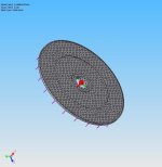
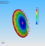
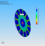
OK, I finally got the parts in to modify my new PC so that the Parallel Port would work with the key for Solidworks. Here is the rotor modeled and meshed for the finite element analysis:
AxilaMotorRotor-Axial-Solid mesh.jpg

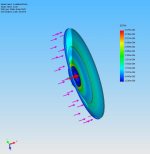
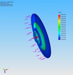
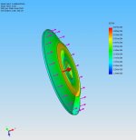
The following are strain contours of the rotor as we increase RPM, there will be some interesting results as we approach the limiting speed. NOTE: I DID NOT MODEL THE MAGNET MASS, so the maximum RPM will be LESS than this analysis shows. This analysis is NOT DONE to the quality level that one must do to definitively determine safe rotor speed. In fact I do NOT KNOW the exact rotor material. So this is for learning purposes only!

Here is the strain graph for 1000 RPM, note it dishes forward. All cases have 500 lbF of magnet pull towards the stator.
1000rpm500lbstrain.jpg

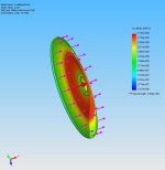
Here is 4000 RPM
4000rpm500lbstrain.jpg

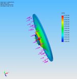
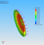
5000 RPM with two views: Note the oil canning changes direction above this speed!
5000rpm500lbstrain.jpg
5000rpm500lbstrain2.jpg

Now to explore where the rotor may start to come apart. Next 6000 RPM
6000rpm500lbstrain.jpg

Now 8000 RPM:
View attachment 3

Lots of RED coming up, we are getting close. Let's look at 10,000 RPM Strain:
10000rpm500lbstrain.jpg

Let's look at stress, I modeled it as 1020 steel. Here is the 10,000 RPM Stress Levels:
10000rpm500lb-STRESS.jpg

Finally right at the yield point, no sane person would run this motor at this speed, and remember, no magnet mass is modeled, so the safe speed will be much less!
11000rpm500lb-STRESS.jpg

And there you have it, the rotor changes oil canning direction with speed; and has a safe speed, I WOULD GUESS, well below 10,000 RPM. Enjoy!
 
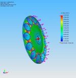
I threw some simulated magnets on the rotor and the speed dropped from the 11,000 RPM area to 6,750 RPM for violation of the factor of safety. Here are the plots to peruse.

6750 RPM 500 lb force pulling rotor into stator, STRESS Plot:
6750rpm500lb-STRESSmagnets.jpg


6750 RPM 500 lb force pulling rotor into stator, Displacement Plot(in Inches):
6750rpm500lb-DISPLACEMENTmagnets.jpg

Finally the Factor of Safety plot on Stress:
6750rpm500lb-FactOfSafetymagnets.jpg

Same caveats as the above post, just a rough analysis... etc.
 
As far as I can tell this hasn't been scooped before, but I stumbled upon these on the GoldenMotor website. They may be of interest to readers of this thread.

JD-PM-24.jpg
JD-PM-24-back.jpg
Disc%20Windings.jpg

PM-24V-75W.jpg


They list several versions, the biggest being a 48V 500W version weighing in at only 2kg. Unfortunately they are brushed. They measure approximately 6" Diameter x 1.5" wide.

Dimensional drawings - http://www.goldenmotor.com/PM-double-magnets.pdf
Dyno Chart - http://www.goldenmotor.com/jd-pm-48.pdf

(To visit source page, select the Java embedded "Printed motor" link from the GoldenMotor website's index list http://www.goldenmotor.com/)
 
so a 4.4 Lb 500 watt motor .... is there a link to where it can be purchased ?

there is this motor ...

HPM5000B-BLDC.jpg


http://www.goldenmotor.com/
 
Hmmmmm.....
 
They have a water cooled version too but I havnnt seen anyone testing them yet. Tempted.. might cop stand go brushed for the 10kw + build.

Ps you can always email them for a quote, though I don't know why they can't be purchased directly
 
great thread... is this little motor still alive? i'm pretty new to electric motors (a few months of sifting through the site) and this is my first post here... after looking at mrbill's data, i had to make myself a spreadsheet of it, and noticed something interesting. if you plot the peaks of efficiency for the different voltages, you get a nice ramp up of power, an exponential ramp up, no less (which i understand occurs with the increasing voltage AND amperage) and maintains a pretty even efficiency at the same time. my question is, can someone just make a controller (or would we be talking microprocessor?) that will vary input voltage (like PWM?) as a function of rpm? (to keep you in the efficiency sweetspot) and then vary amperage by the level of acceleration desired? (i realize that accelerating would affect the efficiency itself, but so would any type of acceleration methinks) or would it just be more EFFICIENT to "go through the gears"? seems that this might negate need of transmissions, at least for cruise conditions, at different speeds. i'm thinking I'll keep the gears though, as they still represent different levels of acceleration, and hill climbing ability. i was wondering if this approach might work elsewhere. is it just THIS motor?, or is it just AXIAL FLUX motors?, or could ALL motors benefit from this ??? it also seems like a workaround to rated power, in that this little guy is “rated” at 500w, but pushes easily close to 2kw. i'm not a speed freak (as a matter of fact, I could be happy with 15 mph instead of 20 mph, the required wattage is about half, so, increases my range by about 50%), i just live in very mountainous terrain.

several things interest me about this motor. first, it seems that someone has the ear of the manufacturer (who seems willing to accommodate different design parameters, and probably works very closely with the people who make the controllers). secondly, the 500w (to near 2kw it seems) output is right up my alley, i'm looking for a build that meets the HR727 requirements (ok 750 would be optimum), and i'd like to do hills (BIG hills, up to 20% grade, maybe 6-8 mph?). thirdly, axial flux design seems like the most efficient i've found so far (although i'm sure MUCH more research is needed, and test results for this motor are not what I hoped for, however, there was one question I had about your data mrbill. is it possible that the drivetrain efficiency, 86%, could have been substantially more or less? you sounded like you were kind of guessing there, even though it sounds about right. I just have little to compare it with, it's rare to see at the wheel output data, but I like it). i like efficiency for a couple of reasons. energy consumption, for one, and two, the avoidance of overheating is appealing. it also seems like (dual) axial flux might be better suited for a coreless, cogless setup (it seems to me like the opposing magnets provide a more "natural return path", as opposed to having to go through a core (armature?) or "pair" of cores to complete a circuit, is this right?). i also like that it's not halbach (so, so much for the efficient return path, lol, but i'm not convinced it's worth it, giving up half your poles). ok, maybe i'm talking about a lot more than just a few design parameters now...

i actually have several questions about design theory, most related i think to this kind of "electrical gearing" as i've heard it called. i like the volt up, gear down tagline, i'm just trying to lose the gears (the mechanical ones anyways). seems like this is just one of the ways (my inclination is more towards larger diameter though, with the possibility of higher pole count and increased torque arm radius) any other thoughts on severly reducing Kv ? (perhaps assuming we're already at max slot fill)

lastly, props to ALL of you, there are some really incredible minds hanging out here. looking forward to many more awesome threads and discussions.

ps, i really am pretty new to this, if anyone has some links to design theory, maybe how changing one variable affects one or more other variables, or advice on where these kinds of questions should, or could, be posted, or answered, i'd appreciate it a lot. many thanks.
 
Back
Top