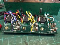
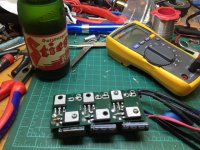
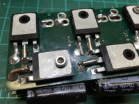
Micro Lebowski Controller - DIY 3kw

No I wasnt modifying the CPU board. The new boards are just the battery bus, fet board and the driver board. That's a good point though. I could add it and get those boards to. But I still have the unpopulated ones here didnt want to throw them away...
 
Animalector said:
No I wasnt modifying the CPU board. The new boards are just the battery bus, fet board and the driver board. That's a good point though. I could add it and get those boards to. But I still have the unpopulated ones here didnt want to throw them away...
if this controller is really meant for 3kW i don't think any temp probe for the controller is necessary.
holes for zip ties are a welcome addition.
 
so i started the battle an hour ago. it WAS A NIGHTMARE. and it ended as i was expecting it. putting too much heat for too long on the parts makes the traces lift from the board. but what should i do. those 6mm thick copper standoff transport heat very well.

i removed the fets with a diamond cutting blade

View attachment 5
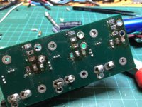
after removing the standoff and some of the pins it looked like that. some pins were stuck because, as andy already mentioned, they were bent on the other side. and covered by solid copper rod.

View attachment 4

IMG_1091.JPG
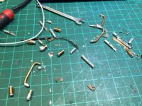
the leftovers. a battlefield :)

IMG_1092.JPG

View attachment 1
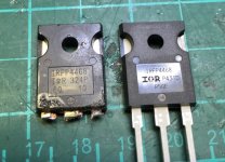
and here a picture to compare the fakes and the real ones.

IMG_1094.JPG
 
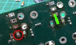
i still couldn't remove 3 pins (all at the same position - the red circled ones) and i don't want to destroy something on the board, so i'll leave them on. and imho it isn't necessary as this pin doesn't need to go to the other side, as it can be directly connected to the other fet - the GREEN line. can someone confirm that ?!

IMG_1091.JPG
 
yeah you can do that but the current path will then b through the board, Through the Vias filled with solder. Having the pin go through the board means the current path is pin - pin (via solder) on the top side. It'll might be ok. those holes are pretty big, and it is filled with a copper leg...

I can send that new replacement base board if you want. or are you going to try salvage that one.? I'll take one with me to work today and try get it sent at lunch..

Andy
 
behind those two holes is one big copper bar so they are connected with 6mm2 copper. what i want to do is: stick the source pin through the hole and solder it and don't bend the drain pin of the other fet but lay it flat one the other's source pin.
that way i do loose one through-connect between the upper and the lower side. that's true. but would that matter? the original drain hole is filled with the cut off pin and solder. so it should make no difference.
sending me a replacement board is much appreciated of course. thanks!
 
A hot air rework station makes this kind of work easier. I also use a heated solder sucker with a squeeze bulb.

About 2 years ago upgraded to a big 125w iron wich has a tip with good thermal mass along with a hakko electric pump desoldering because I knew I was going to do a bunch of tough to solder situations. It sucked to fork out the money, but it has saved me a large amount of time. Then I added a hakko station. I can finally handle most soldering situations... But that was probably $800 in gear.

An ayoue combo station + big iron like an american beauty 125W will make power electronics jobs much easier. Look for used american beauty irons on ebay and score a great deal.
 
i have a hot air station. but i guess i can't handle it properly. would i need to use little air or a lot? and would i use the thin or the thick nozzle?
i also have a big 100w iron with a big tip but the problem here was that there are six standoffs holding the boards together and you can't heat all of them to seperate the boards. i would need 6 soldering irons and 6 hands :(
 
I thought you were just going to cut off the FETs at the housing, clip the legs of the new FETs so only the big flat part at the housing remains, and then solder the FETs on the legs of the old FETs...
 
Great project progress here folks, would be good if boards plugged/bolted together, rather than soldered. Also would be excellent if the FET board module had few other components on it and could be replaced as a module. You could even carry a spare, swap the module, and repair the module at the individual FET level later.

One trick with the hot air systems is the IR preheater. The whole board set needs to be preheated so the hot air is just bumping a local area over the melting point. This heat bath minimizes the local stress and speeds the process. But having to simultaneously melt six massive things is just not going to be easy.

Splicing at the leads as Lebowski suggests is another approach worthy of consideration.
 
Alan B said:
Splicing at the leads as Lebowski suggests is another approach worthy of consideration.
you tell me NOW! ;) i thought of that as well, and wanted to do it. but as there was a lot of solder i was afraid that if could drip inside and cause some shorts, so i did it the hard way. i guess it will be as good as new when i'm done.

the boards are cleaned, the standoffs are cleaned as well and fit inside the holes again. i will solder the standoffs first on the FET board first, and then add the second board.

but first i have to finish another bike. i just can't add a new CA with all the leads dangling out of it. i MUST open it and remove all unused wires and shorten the remaining ones to the correct length. but after that it's a clean job. takes some time though.
 
would be good if boards plugged/bolted together
yeah I wanted to do that with bullet connectors initially, but would have been too high. bolting together is an ok idea, but what's to gain? there's no reason why anything would need to be removable.. (with the exception of fake FETs....)

you tell me NOW! ;) i thought of that as well
I did mention this a while back too I think.. it was how I replaced my one. probably better to pull them out of the board anyway in my opinion... better long term.
 
izeman said:
Alan B said:
Splicing at the leads as Lebowski suggests is another approach worthy of consideration.
you tell me NOW! ;) i thought of that as well, and wanted to do it. but as there was a lot of solder i was afraid that if could drip inside and cause some shorts, so i did it the hard way. i guess it will be as good as new when i'm done.

the boards are cleaned, the standoffs are cleaned as well and fit inside the holes again. i will solder the standoffs first on the FET board first, and then add the second board.

but first i have to finish another bike. i just can't add a new CA with all the leads dangling out of it. i MUST open it and remove all unused wires and shorten the remaining ones to the correct length. but after that it's a clean job. takes some time though.

You are doing a nice job there, first rate!
 
Animalector said:
would be good if boards plugged/bolted together
yeah I wanted to do that with bullet connectors initially, but would have been too high. bolting together is an ok idea, but what's to gain? there's no reason why anything would need to be removable.. (with the exception of fake FETs....)

....

Use plugs for signals

Use bolting for high current

Benefits:

1) ease of construction

2) serviceability
 
Recommendations for reliable plugs for signals?

Suggestions of how / where to bolt the Vbat bus onto the FET board?. You've got me thinking but I don't immediately see a compact way of doing it. Maybe for a10kw controller yes. I'll do one of those next.

Andy
 
i wrote some software almost a year ago, to graph the different parameters while in motor mode.

the software is not 100% done or really tested, school work got in the way unfortunately.

but if you like, i can upload the latest version to dropbox, and you can try it.


almost summer again, so i will dust off my lebowski controller project again.
 
Oh man. I was hoping it was just going to work 100% grrr.. let's think outside the box. Hmm. Brainstorm... Ok outside the box . Outside the box . What's Inside the box? Pizza. Pizza comes in a box. Pizza is round. What else is round? Hmm wheels are round. What can you put in a wheel? hmm. A hub motor. Maybe a mxus3000w. See the logic... It's totally clear to me...

Seriously though. Hope there is another answer waiting out there.
 
Animalector said:
Oh man. I was hoping it was just going to work 100% grrr.. let's think outside the box. Hmm. Brainstorm... Ok outside the box . Outside the box . What's Inside the box? Pizza. Pizza comes in a box. Pizza is round. What else is round? Hmm wheels are round. What can you put in a wheel? hmm. A hub motor. Maybe a mxus3000w. See the logic... It's totally clear to me...

Seriously though. Hope there is another answer waiting out there.

Maybe bandwidth reduction will help, see http://www.endless-sphere.com/forums/viewtopic.php?f=30&t=36602&p=1057529#p1057529
 
Got my new output stage PCB's will post photos tonight. looks kinda cool. I was thinking too I could very easily parallel up the FETs and use 3 of these boards to make an 18FET :D with somewhat isolated phases very easily. it'd be long, but not very wide or tall..
 
Back
Top