
mxlemming
Power poster
- Joined
- Jul 17, 2020
- Messages
- 1,311
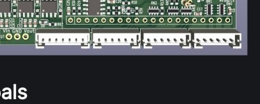
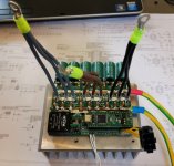
What firmware?Hello, I think I built the latest version v0.6 and I have a problem with the configuration file. The voltage measurement resistor values have changed to 360k and ~7900k. The mosfets I used were mdp10n027. Capacitors 4x 2000uF 100V nichicon. Everything works on small drone engines, but unfortunately not on larger ones. I set the dead time to 250ns. Is there an updated description of the PCB pins somewhere? Unfortunately, I don't currently have an oscilloscope to check the gates.
250ns is almost certainly about 1/3 of what you need. Normally i run 800ns on the MP2
You'll need to set different parameters for motors. Resistance, inductance and flux linkage. It can be run with all sorts of motors, i haven't found a motor it won't run yet.
You'll need to update the resistor divider in whatever firmware to stand a chance.
I recommend IPA and an old toothbrush to clean the board, it's caked in flux and debris in your pic. This will not help.
")


