New 100A FOC controller project

Mihai_F

100 W
Joined
Oct 11, 2021
Messages
166
Hy guys,
As mentioned in my post New Custom Motor Project for Solar Car
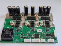
Here i'l describe the FOC controller. It's design begun a year ago, when i started looking into making an single board all smd FOC esc and also started developing the FOC code for STM32 uC-s. A verry big inspiration for code came from MESC code, big thanks' to David. Also the hardware got a bit inspired from MESC board in regard with the close placement of the power FET's.
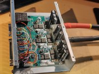
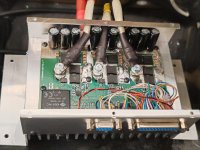
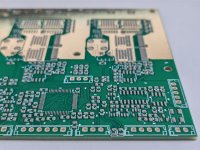
The design is nothing new under the sun, its rating is 100A phase amps, it can be in 60V 80V 100V rating depending witch FDBL86xxx (12 fet design) series FET's are used, dc-dc power brick for HV step down, 150A hall current sensors from allegro (ACS72981), F446 uC, RS232 UART, CAN, ect... At 60V rating the fet-s have 1.1mohm rdson so 2 in parallel will be super low dissipation, but at 100V rating fet-s have 5mohm rdson with 2 in parallel there is still quite some dissipation, so that is why 12 fets, for continuous use and not over heat. Gnd bus power traces have copper plates on top for current reinforcement, positive bus is 2 big fat wide planes on 2 layers. Board is 4 layers, 2oz outers , 0.5oz inners, it sits on a sillpad on its entire surface and then bolted to the heatsink (150x100x25mm has machined surface to clear pins of the THT devices), and aluminum casing, as usual for me :D .
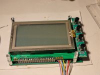
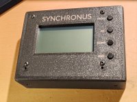
The display is the same setup used on my plane, went with 3D printed case this time... , the code needed some rearrangement of the graphics to show speed and land based vehicle parameters.
I made 2 at once, on 60V rated for my drift trike build and one 100V rated for the solar car. Unfortunately my FOC SW was not mature enough to use in the solar car on the race day, so we used a backup controller (kelly).
I'l come later with measurement plots on the scope.
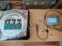
Here are some photos of the boards,
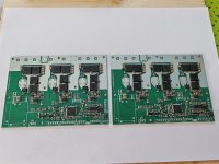
IMG_20240905_104029.jpg
IMG_20240905_165935.jpg
IMG_20240905_170838.jpg
IMG_20240906_114616.jpg
IMG_20240915_221000.jpg
IMG_20240916_235258.jpg
IMG_20240915_013050.jpg
IMG_20240915_221752.jpg
 
i'm back with measurements,
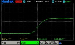
I did the double pulse test, supply 40V inductor 24uH, first did 97A then 127A, then went full hog with 148A and 183A twice, and the software overcurrent protection kicked in and stopped the second pulse. (unfortunately SW protection is not like HW desat protection in my 300A controller for plane, but still cool tough) Then repeated the 127A DPT and analyzed closely the data, it seems fine, no ringing just a 5v overshoot, the shots are inverted, the measurement is for high side Vds.
HS Vds turn on (inverted)
dso_01_01_06_07_57.jpg
HS Vds turn off (inverted)
dso_01_01_06_09_18.jpg
HS Vds DPT second pulse (inverted)dso_01_01_06_05_04.jpg
HS Vds DPT all pulses (inverted), see the supply sagging almost 5v (limited current supply)
dso_01_01_06_03_31.jpg
LS Vgs yellow, Vds green, during PWM-ing about 60A (phase Amps) in a 12uH inductor for one second
dso_01_01_00_40_05.jpg
dso_01_01_00_42_02.jpg
Here is the confirmation of the current 127A logged by the uC, (current was logged just like in MESC code for DPT)
blue beginning of the first pulse 89A
red end of the first pulse 127A
green beginning of the second pulse 124A
second red end of the second pulse 89A
light blue freewill current after the second pulse 78A
D_P_T_5_127A longer second pulse.png
And the 183A one
D_P_T_1_183A_1.png
So far i'm pleased with the results of this hardware.
Next, il put it on my drift trike and abuse the heck out of it, and have some fun.
 
Very nice results. I also use Psof8 mosfets in a few projects and I am very satisfied.

Can you give information about double pulse test? How long do you program the pulse? And how fast was the current control response?
 
Nice. This looks super similar to the first VESC I ever made in layout. You can easily push that to 400A for a few seconds. Unless you accidentally messed something else up on it.

Like the choice of MCU.
 
Are you using the box as a ground? I recommend against that. Arcs to the case/inside the motor from battery and phase wires are very very hard to extinguish and irritatingly common. Don't ground the negative of the battery.
 
Very nice results. I also use Psof8 mosfets in a few projects and I am very satisfied.

Can you give information about double pulse test? How long do you program the pulse? And how fast was the current control response?
You need 2 pulses, one long in order to raise the current, and the second to switch the DUT on/off in that current .For 127A in 24uH inductor at 40V the pulse was ~130us. Over current detect is SW, in 44us intervals , pwm triggering injected ADC for current.
 
Are you using the box as a ground? I recommend against that. Arcs to the case/inside the motor from battery and phase wires are very very hard to extinguish and irritatingly common. Don't ground the negative of the battery.
yep, the box is grounded to B- , mostly for EMI shielding, although the heatsink is isolated from vehicle chassis ground, the electric propulsion has its own ground witch is isolated from vehicle ground. I know and understand what you say about grounding the heatsink/chassis to B-, one plan for future is to have isolated the HV B- from LV GND, and then only LV will be grounded to chassis. In electric vehicles (cars) there is a voltage divider connected to B+ and B- and the middle point is connected to chassis gnd, the ECU constantly measures that with respect to B+ and B- and if it deviates from what it should be (half HVbatt) it throws isolation error and disconnects the main contactor solenoid, to avoid nasty problems.
 
yep, the box is grounded to B- , mostly for EMI shielding, although the heatsink is isolated from vehicle chassis ground, the electric propulsion has its own ground witch is isolated from vehicle ground. I know and understand what you say about grounding the heatsink/chassis to B-, one plan for future is to have isolated the HV B- from LV GND, and then only LV will be grounded to chassis. In electric vehicles (cars) there is a voltage divider connected to B+ and B- and the middle point is connected to chassis gnd, the ECU constantly measures that with respect to B+ and B- and if it deviates from what it should be (half HVbatt) it throws isolation error and disconnects the main contactor solenoid, to avoid nasty problems.
Good that at least the box is isolated from the chassis. Personally I'd never rank EMI concerns above shorting concerns. Both are of course critical for a commercial product but if you're making one offs for fun... Well flames outrank hypothetical gremlins in any circumstance i can think of. What people blame on EMI is very very rarely actually EMI, it's usually crappy ground connections or ground loops or something like that. It's standard practice in most software departments to blame EMI for memory leaks, floating pins firing interrupts, unterminated reset lines, divide by zeros, delay until, while (1){}...
 
... It's standard practice in most software departments to blame EMI for memory leaks, floating pins firing interrupts, unterminated reset lines, divide by zeros, delay until, while (1){}...
yeah that is a good one :D , heard of that

EMI topic for me is to keep it inside and not get out the "box", to protect the radio reception, comms....

There was a team at solar car racing that used some vesc based controller, they had big trouble tuning it to the motor, and it was running verry rough, it sounded like it was working on steam (not joking) , and every lap when they passed by us at stands our radio was buzzing loud, so EMI stuf....
 
Last edited:
Back
Top