speedmd
10 MW
Good post chalo. Thanks for the names / pictures.
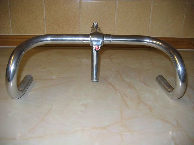
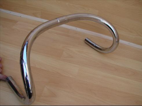
Like the mary and postino bars! Know what to look for.
Like the mary and postino bars! Know what to look for.
shorttyd said:I didn't know different bars had different names.


yeah Kepler , you could easily add a couple biger capacitors in there, or upgrade the stock ones? but with only 800watts being pulled I dont think it would be that much of an issue, whats the power rating on the rc controller anyway?Thud said:Something about all that inductance & ripple crap we fight with & work around with added capacitors.
Just a heads up if some problems arise.


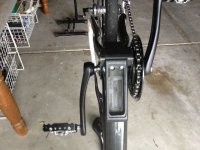
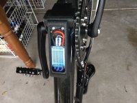
Kepler said:So now with all the main components in place, its time figure out how to keep the wiring nicer and neat.
adrian_sm said:Kepler said:So now with all the main components in place, its time figure out how to keep the wiring nicer and neat.
Simple just run the phase wires down inside the seat tube and seat post. I am sure the carbon fibre won't mind a couple of holes........ much.