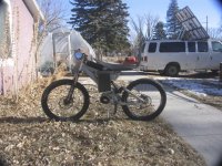
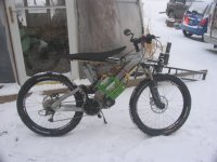
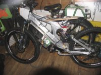
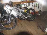
new cyclone 3000 w mid-drive kit?

After taking some measures to eliminate the likely hood of another chain jam occurring from the underside I got the most unusual chain jam. I was riding drifts of crusty snow higher than the bottom bracket on levelish ground when this chain looping event happened. No doubt, the crusty deep snow can push the chain upwards except maybe with the tightest of chains when using the big chain ring in the front and the big cassette on the freewheel. I was not in the tightest chain gearing configuration when the looping happened. You can also get underside jamming from chain bounce.

I have tried several obstruction plates & mechanisms to prevent the chain from getting in the space between the lower stays and the chain ring space [LSCRS] coming from the underside. The Lightning Rod mi-drive design using the 219 kart chain is notorius [I own one] for such chain jams and this is because the chain has pins that protrude beyond the flat plates of the chain. So the protruding pins of the chain can grab the a smooth 10 speed chain and push it into the lower stay-chain ring space [LSCRS]. But I was using the OEM 1/2 x1/8 BMX chain on the C-3000 with a half link. After adjusting the long pin on half link BMX chain to protrude outward as opposed to inwards I figured my stop gap mechanism would be successful. But I still was getting the most unusual JAM.

My first mechanism to prevent chain jams at LSCRS was to attach a plate on the outside of the stay facing the chain ring with enough thickness to leave about zero clearance between the chain ring and the stays. I am sure this worked some of the time but not enough of the time. Reason: The 219 chain with the protruding -- grabbing pins held the the rear chain good enough that it could be forced through this zero clearance space because the motor drive chain ring was deflecting outward during the squeeze through process of getting the chain into the LSCRS. This same jamming process may have been happening with the C-3000 due to that one protruding pin of the half link?

View attachment 8

The first attempt at a stopping mechanism is shown:

View attachment 7

Here is a similar plate is on the LRSB:
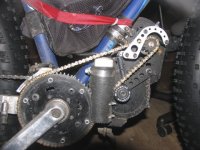
mod IMG_6398.jpg

Because of chain ring deflection this side plate adaption did not work enough of the time to prevent the chain from ever getting into the LSCRS. Here is the current version of such a mechanisms that seems to be successful for the hardtail fat bike equipped with the LRSB.
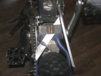
mod IMG_6722.jpg

Another view of the normal plate:

View attachment 4

So far this normal plate is working but with enough motor BB chain ring deflection a large enough gap would allow the chain access to the LSCRS. It is that 219 kart chain with the protruding pins that grabs very effectively.

As for the full suspension bike with the C-3000 the same cross frame/stays normal plate as used on the hardtail fatbike was not fit-able. So a different plate fitting using channel aluminum was made that clamped on the underside of the stays:
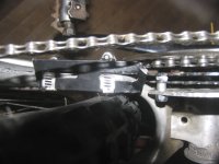
mod IMG_6720.jpg

To further close the stop gap space a cross bolt spacer/blocker was added to the annular ring which is used to prevent inward falling of the chain near the stay.
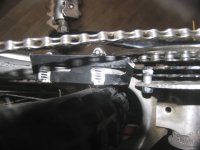
mod IMG_6720.jpg

Even this closeoff of space was not fully adequate as there is a gap between the bolt and the small chaining. But even with not much space, still the unexpected can happen? Here is a view of the little bit of space between the cross bolt and the small chain ring.
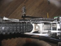
mod IMG_6721.jpg

Recall the unusual chain looping event I mentioned at the start of this post? Here is what was happening in this little bit of space: Probably because I was running a narrow wide chain ring on the small ring the slackish chain had some tendency to stay attached/touching the lower side of the chaining. This effect and the effect of snow pushing the chain upward results in such a condition to fit and push the chain into the small space between the cross-bolt and the chain ring. One would think the pull of the chain would readily pull it out of this space but that did not happen as the scale of the space was such that once the chain was pushed through the gap, it took a configuration that with gravity kept it in such a loop. Oddly the chain would flow as if it were on a small pulley in this location. It would stay there with all throttle action and make plenty of noise -- never jamming. After getting the chain out it soon was pushed by snow into this configuration again. I then shifted gears to the chain ring set-up giving the tightest chain and it did not happen anymore. But I do not always want this gearing so I needed one more fix to get the chain blocker working.

Here we see the fix:
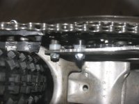
mod IMG_6729.jpg

So much for solving detective like mysteries but so far there is no commercial device to stop gap such chain forcing events which can happen when riding in deep crusty snow.

There is another easy fix:

Run a tight chain and a one speed gearing.
 
After my above post I began wondering how it was that I never got chain grab/jam between the stays and the close chain ring on my Stumper Jumper XC. One look and it was obvious. There was plenty of space between the chain and frame for the lifted or bounced up chain to just drop back out.

mod IMG_6735.jpg

Usually a big space here [between the chain stay and the biggest chain ring ] means a narrower space between the stays and hence not as wide of a rear tire as you may like.
 
After a total lack of help from our local USA Sabvoton Sinewave Controller dealer-importer -- customer service there sucks, one could say it does not exist. I decided to try to install an older 96v Kelly Controller on one of my Cyclone 3000 motors. As usual I got puncual and to the point replies to my emails to Fany of Kelly controllers.

Over the weekend I kept getting error code 4-2:

From the manual on error 4-2: 1. Incorrect or loose wiring or a damaged hall sensor. 2. Also be caused by incorrect hall angle configuration (60 degree or 120 degree)


From another email:


I have checked the Hall wiring with a continuity multi-meter from the end of the Kelly Hall harness leads to where the 5 Hall wires are bundled and enter the motor. I did this noninvasive like testing with a sharp needle to penetrate the last visible hall wire sheaths. No wiring problems in this zone. I also added a conductive grease to the wire connection junctions.

The Hall angle is known and is entered as 120 degrees. Sixty does not work.

Each time I get done with a Kelly Test Run I am able to hook up my OEM controller and the mid drive motor runs fine -- on pavement and I do riding with the existing Halls & their wirings. The motor has 8 steel magnets. The motor is a Cyclone 3000.

here is the reply from Fany:

If the motor is from Cyclone,we may try to use 12V instead of 5V for the hall sensors.
This type of motor has some problem with the hall sensors signal.

Thanks,
Fany

And as for how to get the 12v hooked I asked:

Hi Fany,

the 12v instead 5v sounds worth trying. Is the following wiring setup satisfactory for getting and using 12v on the Hall sensors:

Reconnect the black and red 5v wires going to Halls using from pin1 of J1 12v to the red Hall wire and from p7 of J1 connect to the black Hall wire?


From Fany,
HI,

NO,Actually I tried 12V for the hall sensors of Cyclone motor for many times.
It seems these motors only can work when we use 12V for hall sensors.

The ground wire is still on J2 pin14.You don't have to change the ground because they are internally connected.
Please just use 12V for the hall sensors instead of 5V.

Thanks,
Fany

It seems with Kelly you get knowledge with punctual customer service -- I like it.

I have got powerful rotation on my Kelly controller-Cyclone setup now. I wonder, does the Sabvoton actually need 12v on the Halls instead of 5v to work good on the C-3000? Maybe I will buck convert the 5v to 12v making a common ground as the Sabvoton does not have an internal 12v 30mA power supply like the Kelly.
 
I had a similar experience with Kelly. If I called them during their working hours which for me me was conveniently early evening, Fanny would get back to me in minutes. It was more like online chat than Email.
 
cheekybloke,

thanks for pointing me to right search words [ chain suck device] A mechanic at the bike shop searched for such an item for me and could not find any of these items. I do not remember the word combos we tried.

A lot the google pictures show them on hardtail bikes for which they are usually quite easy to make at home. With rear suspension you do not want them moving into & against the chainrings and these bikes tend to have less good attachment locations. I will study them over and see if some of them are particularly well suited for my problem bike.

For what its worth, I usually do not drill & tap into the bike frame but clamp. My bikes would be full of holes for all the changes and improvements I make and try. Because of that stipulation some of these Chain Suck Devices shown in the google search are not for me.
 
Multistar High Capacity 6S 16000mAh Multi-Rotor Lipo Pack back on sale at $71.99


https://hobbyking.com/en_us/multistar-high-capacity-6s-16000mah-multi-rotor-lipo-pack.html

Skaiwerd » Mon Dec 19, 2016 10:41 am posted the last Hobby King sale and I sprang for those modular Lipo cells on sale buying 6 packs of the 6s 16Ah size. The granularity of this particular LiPo batteries size is both a curse and a blessing depending on your mounting options. I have been a DIY battery builder; spot welding 18650 cells in the past but this Hobby King price is less than half what I would have to pay for bare 18650 cells including shipping. And it takes a lot of 18650's cells in parallel to get the whopping high amperage the Multistar Multirotor batteries can produce. Battery data shows I may get only a little more than half as many charges with LiPo compared to high quality 18650's. Even at this scale of molecularity a battery change out seems simpler than some to many 18650 configurations.

I later sprang for 2 - 4s 16Ah LiPo's that were on sale to give me a nominal 81.4 v at 32Ah -- this big set of batteries make for a long range edirtbike. Maybe this many bricks is a little heavy but with the scale of modularity I can drop a portion of the pouch packs easily and still have amazing peak performance.

Mounting batteries of this width on the bike was a challenge. But I now realized that on most full suspension bikes there is a place for a universal battery platform that interferes little with pedaling or handling. I will soon get a post up on this sneaky revelation[2 me].
 
DingusMcgee
Putting 6 of the multistars into my frame has become a big challenge to me. I'd like to do 2 separate packs of 3 batteries each, that's 75volts fully charged. I did ride with some eBay floureon brand lipos that were only 13ah and about $100 each including shipping. Obviously the the multistars are a better deal at the sale price. I did have a cell fail with the flooreons and had to pedal home. It was refunded but I did have to send it back. It's probably time to consider a special jumper cable to go from three batteries to two batteries in case of such failure. Some may say that getting half the charge cycles is not a big deal as the technology changes you'd want the new stuff later on anyway.
 
Putting 6 of the multistars into my frame has become a big challenge to me
Yes, I would believe so since you say "into my frame" instead of "onto my frame" as these things are the size of bricks and at that scale of increments there are not many choices to get all the batts in some zone lacking brick modularity.

For my battery configurations there are 4 criteria that I must meet:

1. The batteries have to be between the wheels and as low as possible -- in the triangle area. On this constraint, edirtbike builder/designer ES member
Recumpense agrees.

2. The batteries need some form of protection -- a shell or covering.

3. Their position cannot interfere with my riding style. I ride both standing, siting and leg straddling while some what forward on the enduro seat.

4. The battery position cannot interfere with suspension travel for my riding style.


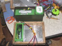
With these 4 constraints in mind I do battery mock ups with the bike laying down or upright whichever is suitable to the bricks staying in place. So most of the rest of this post will be photos of some of the trials and errors:

Let the mock ups begin.

mod IMG_6693.jpg

mod IMG_6694.jpg

mod IMG_6695.jpg

mod IMG_6696.jpg

mod IMG_6697.jpg

mod IMG_6698.jpg

mod IMG_6701.jpg

View attachment 9

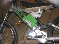
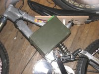
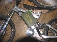
This ammo can arrangement was a little like a motorcycle gas tank but the ammo can position mostly interfered with my standing lateral motion while riding terrain. It was 9 inches wide -- It seems 6" wide is workable but with this interference at 9 inches wide it was back to the mock up routine.

mo IMG_6703.jpg

mod IMG_6704.jpg

mod IMG_6705.jpg

mod IMG_6706.jpg

mod IMG_6707.jpg

mod IMG_6710.jpg

View attachment 2

The universal battery platform I was talking about is quite visible in pic 6707. It is the aluminum plate fastened to the down tube with gear clamps. With the bricks at 3" wide on each side and the down tube 2" wide we have a width of 8" and with this pack placed out of the pedaling zone [ the bricks can be positioned upward along the downtube] there is no interference with lateral motion when standing and pedaling.

I have found the Velux skylight window flashing kit has some aluminum 5052? flashing stock that folds quite well. The covers for the 3 x3 alum channels were made of this flashing.

mod IMG_6740.jpg

mod IMG_6741.jpg

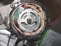
Note the thermistor wires coming out of the motor end cover on the upper right quadrant -- another story.
 
Some time ago Sather informed me of how quickly he burned up a C-3000 motor. Well yesterday I was cruising past a large vacant lot that in the summer has large piles of dirt that the trick & BMX riders use. It is now covered with deep crusty snow. I decided to do a diagonal across its corner. The deep snow was lugging the motor quite a bit. About half way through at 125' feet of milling I stopped and felt the motor cover and it was just warm, but ambient was -2F. Okay continue with the diagonal to the dry pavement. Just the before reaching the pavement I seen smoke coming off the phase wires and soon realized the motor was toast. Is it the high AMP Kelly controller that gave the motor too many amps? Kelly programmable controller do have have motor temp monitoring setup with temp choice for motor shut down features. And it has features limiting motor current. Who would use those?

Yesterday I took the C-3000 motor out of the hardtail and put it into the Big Hit build. The gummy aluminum motor freewheel adapter was to tight for using the lightly taped pickle fork method. I heated the alum adapter with the heat gun to quite hot and then the light ball pin hammer tap on the pickle fork easily slid the alum adapter off. Those 1.375 x 24 adapters sold by Staton are made of steel and seem to have a looser fit than the alum from Cyclone -- but still snug.

But with two additions:

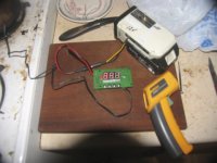
I decided with the extra amps I can give the motor with the Kelly controller it was time to hook up a thermistor. I now have hooked up the Kelly KTY 84-130 with the 1K ohm pulldown resistor and found out the Grin 10K NTC thermistor which is the working mate to the Grin CA3 dashboard also works with the fish tank temp controllers I get on eBay from China[FYI Gman 1971: some time before Phife used one of these to monitor bike temps, I was monitoring solar hot water heating setups with them in a similar fashion to how it is used on bike motor temp monitoring] With some boiling water tests I found the Grin thermistor gets to boiling temp read out about 3 sec faster than the one sold with the the Chinese eBay fish tank temp controller. But in a treadmill like test with both the Kelly thermistor hooked to the Kelly controller and the Grin thermisor hooked to the eBay fish controller and both of them epoxied to the innards [JB Weld] of the Cyclone motor the Kelly controller reached the 65 C, the designated shutdown when the Grin was reading only 48C. The grin is enclosed in a plastic sheath and as it is somewhat bigger than the Kelly thermistor so it could not be mounted within the copper coil loops' steel frame of the motor electromagnet space. Beside who knows if the Grin covering is needed? If I cut off the sheath it would fit into a smaller, hotter space and maybe not work? I may need an additional 12v power source as the fish tank controller just may take more than the 30 mA limit from the Kelly controller which has part of that quantity of current going to the Cyclone Hall sensors.

mod IMG_6739.jpg

I like the fish tank controller because you can monitor what the present motor temp is but the Kelly cannot display this info, except maybe with the CANBUS? The Grin thermistor does work with the CA3 and can do this sensing & monitoring but I do not have the CA3 mounted yet as it's user set of progammable features overlap with what one can do with a Kelly controller.

Yes, this burnout may have been quicker than Sathers' burnout?
 
DingusMcGee

Please tell the amount that was the "extra amps" that cooked your cyclone motor with the Kelly controller? This info could help those of us out that may go beyond the standard stock controller, thinking about the luna 50amp bluetooth controller. Those multi stars are only 10c rated discharge correct? So doing the math and cutting that figuring half to be on the safe side the batteries are only rated at 80A, where you below that? I may be incorrect in my amperage figuring please forgive me if so.
 
The multistars can do 160 amp [10 x 16 ah = 160 amps} and give a 20sec burst of 320 amp according to specs. And since we have 'em doubled we can get long bursts at 2x160 = 320 amps, clearly way more than the C-3000 can take. I had the Kelly controller set at 75 amp which when with a fully charged battery is 75 x 75 = 5625 watts did the damage. I also was in too high of a gear for that terrain -- yes I thought the trip would be so brief -- it was. So we know if Gman1971 braggs of 6.5 kw on the C-3000 its duration is very brief. My findings concur with what the Russian Test of Chupa discovered: the Cyclone 3000 at 6.5 kw is about 55% efficient -- so one hell of a lot heat is produced.

From page 35 of this thread your can find what Chupa said:

The EFF with 5kw power input is a approx 70% on 63v. if you will add 6.5kw , the EFF will be approx 55%. It means that about 3 kilowatts will go to heat.
It seems to me 6.5 it is possible to give on dispersals quickly. It is long to give 6.5kw not expediently as nearly a half of energy goes to heat.
Yes, I suppose you can briefly run 80 amp but you would have a far quicker shut down with a monitoring shutdown thermal sensor epoxied very close to the copper coils where the heat originates as the heating can happen so quickly that the outside of the case can be totally cool. The duration you can safely run at 80 amps may in short bursts get you to > 60 mph -- you know gman1971's claim to fame -- just do not give much practical value to buying such a controller for this measly motor.

I have ran a 40 amp OEM controller for more than a year but to get the long range trips I wanted to do I needed more capacity. I suspect I will set my max current at 50 amp -- now that I have thermal shut down available. I used this controller previously on a Cromotor but not enough curvy pavement around here to enjoy such high speed riding.

I have no need to go faster than 45 mph. When gman1971 got his 60 mph ride he was likely going downhill with a tailwind, pedaling his ass off and drafting his wife in a car equipped with a tail windshield and he was following her 2 inches from her rear bumper -- We never heard this likely true story as with him he spares us the details -- Trump like -- maybe give us a tweet?

Is it about time for his Chain Life Tweet?
 
DingusMcgee
Thanks for the info.
As I thought I'm in the clear with that 50 amp controller. Were your phase wires the stock standard gauge and length with connector? I have shortened mine and removed the plug, but the gauge is stock. In your case thicker gauge wires wouldn't have helped, probably just move to the next weakest link, perhaps? I know the motor fried not just a phase wires.
 
The inside of the motor copper wire coatings were black and flaky with the cable ties that hold the Hall sensors melted and apart. The motor ran very feebly after the burn and helped get me home. Bigger phase wires would get more current to the motor coils quicker! And maybe with little melting or smoking.
 
Russian Test of Chupa discovered: the Cyclone 3000 at 6.5 kw is about 45% efficient -- so one hell of a lot heat is produced.

Where did you see Chupa say 45% efficiency ? looking at Chupas charts this motor is still very efficient up to 5kw input at 85v input it still around 75% efficiency.

http://electrotransport.ru/ussr/index.php?topic=34238.0

You don't want to run this motor at low voltage and high current though as the winding resistance is very high, i also see on their at 33v 2400w input the efficiency is only 57.7% but i cannot see anywhere as low as 45% did you make that number up ?
 
Alex07,

efficiency = output/input; go figure


At max power its efficiency cannot exceed what Thevenon's equivalent power circuit predicts and that is 50% efficiency. With the slightest bit of torque increase from what it is at max power for a given voltage the efficiency goes towards 45% or less.

See: PM Motor theory - formulae etc.

https://endless-sphere.com/forums/viewtopic.php?f=30&t=16376

You say did I make the figure up? I ask do you have patience enough to search this thread? There are more than 2 citations in this thread of what Chupa said.
 
Sather,

here is picture of the fist tank temp controller setup with the thermocouple in boiling water elevation = 7200'. It reads 94.1 C = 201F. The Fluke temp sensor read 183F . The fish temp controller has not been calibrated. It has a provision for that calibration offset.

mod IMG_6742.jpg


Here is the eBay links for one of these:

http://www.ebay.com/itm/50-110-C-DC12V-Temperature-Thermal-Control-Switch-Relay-Delicacy-NEW-1pcs-/182432083313?hash=item2a79ccad71:g:WPAAAOSwUKxYhsGP

search: temperature controller 12v

note the 110C.
 
Sather,

Yes, the price is excellent.

on my tests the Grin thermocouple/thermistor used on 12v temp controller was about 3 sec faster to reach boiling temps in water than the Chinese OEM thermocouple/thermistor -- on the Chinese monitoring circuit. And the Grin was about 17C degrees behind the Kelly thermistor going to 65C.

Because of the slower response time of the Grin and the Chinese OEM thermocouples compared to the Kelly you may want to set your max temp lower -- 15 -20 degree C?

There is a relay on the 12v temp controller that you can run your throttle signal through and it will shut off/open the circuit of it at 1 degree C over what you set -- automatically. Some of these controllers have reset choices of 1, 5, 10 and 15 C degrees lower that the open circuit choice to close the relay after reaching the set high and cooling. They are field programmable.
 
Looking at building an E-bike for the 3.5 mile each way commute I have to work. I just bought 4 X 7S 5000mah Lipo packs from Hobby King just to use for power. This will be my 1st attempt at a bike build of any type but I do have a long background in motorcycle and auto customizing so this fits right up my alley.

Anyway, I've been looking at all the possibilities and different motor/drive systems. I was going for the simple hub motor and almost pushed the PayPal button but I kept looking around. Lately my mind has come over to the Cyclone 3000W mid-drive kit. I look back at the 1000w-1500w hubs and the size and price and then back at the Cyclone. I think I may have finally eased my mind here.

So my question is, with the stock speed control that comes with the kit and a 14S 10000mah Lipo battery pack, wat kind of watts do you think this will put out? BTW, I'm installing this on a full suspension bike with 26" wheels.
 
14s is about 52V, so you'll be at around 2400 watts continuous. That's what I run, and it's tons of fun.

CobraJet said:
...with the stock speed control that comes with the kit and a 14S 10000mah Lipo battery pack, wat kind of watts do you think this will put out?...
 
I was looking at some of the options available to buy.

One thing I don't know is the BB. I see some are Standard Square Tapered BB and some are ISIS BB.

What are the differences and why would you use one over the other?
 
Back
Top