New Lebowski disciple!

Marc, you will not miss anything in v2.30 compared to v2.40 besides the temperature functionality.
But in my opinion this is a great improvement, because it allows a precise safety control for the important components.
I soldered a 4K7 resistor and 3 wires under the PCB, will try to make a picture of it. No need for a special v2.40 PCB (KiCad-file posted by Lebowski: https://endless-sphere.com/forums/viewtopic.php?f=30&t=57877 )

If Bas really manages to find a nice, efficient and safe (!) way for field weakening in v2.50, this would be so awesome... I hate myself for not being able to support him more.
By the way: We had a closer look at the other quite brilliant controller on the market, the Adaptto (ES-Post also here: https://endless-sphere.com/forums/viewtopic.php?f=30&t=61484 ).
The Russian guys seem to follow exactly the same design rules for the power stage as promoted by Lebowski: Reduce inductance to the absolute minimum. Difference: They use normal electrolytic caps instead of fast film/ceramic caps used by Lebowski and Doc Bass in his modded Adaptto.
Cheers, Marcel
 
Dan: The Quantya doesn't need a new controller, the Alltrax 7245 is made for up to 20 cells (84V_max). It has to be reprogrammed for the higher voltage limit, that's all. If you want to keep the original 48V main relay, a resistor (~150 Ohm) is needed for the relay coil. Similar mod for the 48V voltage indicator/switch on the tank.
Battery: Remove BMS, add 6 cells to the 14 original cells, use thinner isolating pieces between the cells. Now the 20 Kokam-cells fit into the original battery case.
Details and pics on demand (PM). Cheers, emmgee
 
Back to the topic of this thread: Here are pics of the little modification for the Lebowski-board v2.30 to be used with the Lebowski chip v2.40 (or now v2.50) with temperature control.

20151103_173444_Board_v2_30_mod_for_tempsensors_01_low.jpg
 

Attachments

  • Board_v2_30_mod_for_tempsensors_01_low.jpg
    Board_v2_30_mod_for_tempsensors_01_low.jpg
    209.9 KB · Views: 1,993
  • Board_v2_30_mod_for_tempsensors_02_low.jpg
    Board_v2_30_mod_for_tempsensors_02_low.jpg
    244.4 KB · Views: 1,993
Maybe this shows it better: 8 temp-sensors DS18S20 can be connected in series. Individual programming is possible. Very useful and nicely implemented by Lebowski!
Board_mod_for_v2_40.JPG
 
Yes, I forgot to mention that, Lebowskis documents are perfectly updated. My info is only valid for the ones (like marcexec) who have the 2.30 board and would eventually use an updated chip. This is easily possible with that small modification.
 
Got finally around to have a basic setup, some eye candy:


Controller board seems fine, connected up and did basic programming, yay! :mrgreen:

The problem is, my power stage all disconnected takes about 12.5A (could be maxing out DMM range), which made me think of a short, but measuring (note: cheap DMM) builds up to ~120kΩ.
It's powered by 50V SLA for the test, I'm using IRFP4468PBF FETs. Any ideas what could cause this?
 
With the power stage disconnected the power stage alone takes 12A ? Is this including the driver chips or just the FETs ?

When the gate is disconnected you can never be sure what a FET does, it can be totally off but also kind of half on. Same goes for the drivers, with an un-connected input it all depends on the driver design what it does.
Looking at the picture the gates of your FETs are unconnected.... So, best is not to have anything in the power stage disconnected. Since the current sensors are not on the PCB, make sure their polarity is correct and that they match with the output stage (so current sensor A must be in output channel A etc).

Since the 4468's have a larger input capacitance than the 4115's I use, did you change (half) the resistors in the gate drive ? It may be OK with the original resistors I used, but I cannot guarantee this... start with a decent amount of deadtime (1.5usec) and work you way down, keeping an eye on the battery current.
 
Lebowski said:
With the power stage disconnected the power stage alone takes 12A ? Is this including the driver chips or just the FETs ?

When the gate is disconnected you can never be sure what a FET does, it can be totally off but also kind of half on. Same goes for the drivers, with an un-connected input it all depends on the driver design what it does.
Looking at the picture the gates of your FETs are unconnected.... So, best is not to have anything in the power stage disconnected. Since the current sensors are not on the PCB, make sure their polarity is correct and that they match with the output stage (so current sensor A must be in output channel A etc).

Since the 4468's have a larger input capacitance than the 4115's I use, did you change (half) the resistors in the gate drive ? It may be OK with the original resistors I used, but I cannot guarantee this... start with a decent amount of deadtime (1.5usec) and work you way down, keeping an eye on the battery current.

Found the issue - wrong polarity. I had it built like you on the pictures, even the same wire colours, but had brown as ground, not blue...
Simple change of the elco sorted this out. :lol:
Will bring work laptop to work on the controller while on the bike the next week and report back.
 
Ehm, are you sure just changing the power elco polarity is enough, is the polarity of the FETs OK ?

My reasoning for the colors was, well, typically ground is blue and positive is red. So I used brown for positive as its kinda close to red.
The wiring I use comes from standard 2.5mm^2 household wiring where you have brown, black, blue, grey and green/yellow....
 
Lebowski said:
Ehm, are you sure just changing the power elco polarity is enough, is the polarity of the FETs OK ?

My reasoning for the colors was, well, typically ground is blue and positive is red. So I used brown for positive as its kinda close to red.
The wiring I use comes from standard 2.5mm^2 household wiring where you have brown, black, blue, grey and green/yellow....

Yep, I was and just confirmed it. The high amperage was due to the wires being backwards in my mind and the elco put on accordingly, turning it around allowed me to swap +/- to match yours. Massive thanks for your work here are in order - I learned a lot from this project (and the Zephyr :)).

I did a bit of testing tonight outside on the bike (at 5°C), calibrated throttle, made some measurements but couldn't get the motor to spin, it was jumping between drive_1 and drive_2 when out of setup (wiggling of course), both sensored and sensorless, deadtime 1000 & 2000 ns tested.
I'm not too worried, the 4 SLAs probably sagged too much to turn the C80100, which is also still connected via a belt to it's sibling and the gearbox...

I will repeat with the 6kWh AESC pack when I get the chance and tune with the motor on it's own - need to order some wire lugs for the 10mm2 cable I use. Can I actually add/remove the setup jumper while powering the controller?

some snippets:
Code:
a) PWM frequency: 21kHz
b) deadtime: 1999ns
c) dutycycle testsignal: 50%
d) toggle high side polarity, now active HIGH
e) toggle low side polarity, now active HIGH
f) test PWM signals

g) autocomplete

h) loop sample frequency: 41.03 kHz


a) current sensor transimpedance: 10.00 mV/A
b) maximum motor phase current: 24.9 A
c) maximum battery current, motor use: 21.9 A
d) maximum battery current, regen: 21.9 A

e) autocomplete

f) HF current, base level (HF only): 1.2 A
g) HF current, proportional factor (HF only): 1.0000
h) maximum phase current in drive 2 (HF only): 11.8 A
i) phase current for forcing motor position: 4.9 A
j) maximum shutdown error current, fixed: 6.2 A
k) maximum shutdown error current, proportional: 3.0 A
l) applied braking current (phase) on direction change: 0.0 A
m) offset filtering (phase) current limit: 0.0 A


a) erpm limit, forward: 69.99 k-erpm
b) erpm limit, reverse: 6.98 k-erpm
c) accept direction change below: 6988 erpm
d) transition erpm drive 2 -> 3: 6988 erpm
e) transition erpm drive 3 -> 2: 6462 erpm

a) battery voltage: 50.0 V

a) restore calibration, autocomplete
b) perform offset measurement
   sensor a: -2562.5 mV
   sensor b: -2562.5 mV
   sensor c: -2562.5 mV
c) perform gain measurement
   channel a: 66.66 %
   channel b: 66.66 %
   channel c: 66.66 %
d) online gain calibration update rate: 3.995 %


b) perform offset measurement
   sensor a: 0.0 mV
   sensor b: 0.0 mV
   sensor c: 0.0 mV
c) perform gain measurement
   channel a: 122.05 %
   channel b: 195.88 %
   channel c: 220.92 %
d) online gain calibration update rate: 0.000 %


a) restore calibration, autocomplete
b) perform offset measurement
   sensor a: 0.0 mV
   sensor b: 0.0 mV
   sensor c: 0.0 mV
c) perform gain measurement
   channel a: 121.97 %
   channel b: 202.21 %
   channel c: 213.93 %
d) online gain calibration update rate: 0.302 %

b) throttle current filter -3dB freq: 100 Hz
c) error current 50% step response time: 5.005 msec
d) induction position filter 45 degree delay speed: 28.30 k-erpm
e) drive 2 speed filter 50% step response time: 228.4 msec

b) throttle current filter -3dB freq: 100 Hz
c) error current 50% step response time: 5.005 msec
d) induction position filter 45 degree delay speed: 28.30 k-erpm
e) drive 2 speed filter 50% step response time: 228.4 msec

b) FOC measurement current: 12.4 A
c) FOC measurement erpm: 56.35 k-erpm
d) perform impedance measurement

 measured inductance: 108.0 uH
 
some things definitely not OK:

Code:
a) erpm limit, forward: 69.99 k-erpm
b) erpm limit, reverse: 6.98 k-erpm
c) accept direction change below: 6988 erpm
d) transition erpm drive 2 -> 3: 6988 erpm
e) transition erpm drive 3 -> 2: 6462 erpm

I suggest:

c: 200
d: 1500
e: 500

also not good:
Code:
a) restore calibration, autocomplete
b) perform offset measurement
   sensor a: 0.0 mV
   sensor b: 0.0 mV
   sensor c: 0.0 mV
c) perform gain measurement
   channel a: 121.97 %
   channel b: 202.21 %
   channel c: 213.93 %
d) online gain calibration update rate: 0.302 %

just restore calibration and leave it at that, typically you don't need (and it is better not to) offset calibration and/or gain measurement.
 
I had a bit of time and the sun was shining, so hooked up the controller today. Some pics of the rudimentary setup:


I made the changes in d) and f). Stupid question (1) at this point, the motor doesn't have to be present for "a) restore calibration, autocomplete", right?
Mode is "Hall sensored, with recovery", I upped the current settings a bit:
Code:
a) current sensor transimpedance: 10.00 mV/A
b) maximum motor phase current: 24.9 A
c) maximum battery current, motor use: 21.9 A
d) maximum battery current, regen: 21.9 A

e) autocomplete

f) HF current, base level (HF only): 1.2 A
g) HF current, proportional factor (HF only): 1.0000
h) maximum phase current in drive 2 (HF only): 11.8 A
i) phase current for forcing motor position: 9.9 A
j) maximum shutdown error current, fixed: 9.9 A
k) maximum shutdown error current, proportional: 3.0 A
l) applied braking current (phase) on direction change: 0.0 A
m) offset filtering (phase) current limit: 0.0 A
So I fired it up and have a bit of wiggling and humming, occasionally even flashing into Drive_3 (not sure if visible in the video, but it happens):
[youtube]Xj9DGHPQMQk[/youtube]
Stupid question (2) at this point - the controller will automatically detect the phase/Hall combination, right? Couldn't find it in the manual and think it was one of the features :) I tried swapping the phase wires anyway with no real difference.
 
Marc, I think you are right that "f) autocomplete, restore calibration" doesn't need the motor connected and that the hall sensors are automatically assigned to the phases.

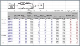
But maybe Lebowskis remark about the FET capacitance is relevant for your problem. Approx. 100nC (lebowski with IRFP 4115) vs. ~450nC (your IRFP 4468) seems too important to leave the resistors for the gate charge/discharge unchanged. If I understand this correctly (electronics noob...), Lebowskis charge/discharge times with the 33/10 Ohm resistors would be 287/67 ns. With unchanged resistors this would mean 1290/300 ns for the IRPF4468, probably too long even for a very long deadtime (you choose 2000 us? Lebowski ~600 ns).
Bridging the R98 (33 Ohm to 0 Ohm) and leaving R99 (10 Ohm) would give 300/300 ns.
Replacing the resistors: R98 (to 3.3 Ohm) and R99 (to 4.7 Ohm) would give 240/141 ns. with charge/discharge currents 1.9/3.2 A. But I don't know where the realistic long-term current limit is for the FET Driver IRS 2186 (specs say 4A?).
FET_charging_lebowski.JPG
Savvy people around to confirm these thoughts?
 
Ah yes, I've seen you choose 15 Ohm and 4.7 Ohm to drive IPFP 4568 (typ/max 151/227nC) resulting in charge/discharge times of ~263/63 ns.
With IRFP 4468 (typ/max 360/540C) charge/discharge would be doubled. Discharge current with 3.2A still in an acceptable range. So the problem must be somewhere else.
 
It would be easier for me to see what is going on if you post the hex (menu z option b) and remind me what version you have ?

For the hall mode to work properly first it needs to be calibrated. For this hall calibration must be enabled in the hall sensor menu and
online save must be enabled in the save to rom menu (menu z). When you then power in motor mode it will try to run the motor sensorless
(and it will determine the relationship between the hall signals and the motors electrical phase). Once the motor is running at speed,
while the motor is running press setup to save the measures hall relationship.

To get the motor to start sensorless it is easiest when the motor is able to start with no mechanical load. The parameters affecting the start
are the wiggle rate and amplitude in the misc menu, some experimenting is necessary here. In a bike like yours it may be easy to
get the motor going by helping it a bit (bike on center stand, in gear, give a bit of gas and move rear wheel). Keep in mind that the motor
may want to go in reverse, then swap 2 out of 3 phase wires.
 
Thanks for this (and the PM).
I tried the above and didn't get much different results, eventually tried HF Tone only after which a FET blew up (and 2 resistors on the board burned out).
After I put my frustration aside I started rebuilding the power stage, which I now suspect to be responsible as one of the unaffected FET's connection came lose when taking it off the heatsink.
Lesson learned: sand down the copper plate properly, the flux wasn't enough.

The copper plate took a hit so I'll have to cut a new one next, probably a little shorter and the caps positioned on the upper edge for easier soldering.
This should also make packaging for my planned 12FET "Production" version a little easier.
Some pics:
 
I have taken the powerstage apart and 5 of the FETs are blown. Good thing I have spares - 4 of them :(
I'm thinking the IRS2186 drivers are blown, too then. I tested them for resistance between pins 1,4,5 & 8 and had readings all over the place, at least compared to the one in the DC/DC.
Any structured method to test them or just dump them to move on?
Anything else that might have gotten damaged?
 
What I would do is to replace the FETs but leave the 2186's in place. When powering up, make sure you use a low amp fuse (2 A ?) or a
current limited lab supply. Put the controller IC in setup mode and use the PWM test function to see whether all output signals look good.
Do not use a motor but leave all 3 outputs open. Look at them with a scope for 5, 50 and 95% dutycycle. All signals should look as you would
expect, if not replace the 2186. In my experience 2186's are hard to break.
 
Back
Top