PWD's Yamaha XV250 Virago build

pwd

10 kW
Joined
Oct 11, 2011
Messages
890
Location
Ontario, Canada
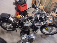
I've got a 2012 Yamaha XV250 I want to convert to electric:

IMG_20240407_153750968_HDR.jpg

My goal is to have an electric conversion I can ride around town (not planning for much highway use) for fun. My Grom clone build already fits this role but is not licensed and insured. I'd like to have something I can ride without worrying about getting pulled over for no plate etc... I am aware I will only have a fraction of the range with limited space for a battery (being on the small side for this style of bike); but the plan is to have at least twice the horsepower of the stock 21HP xv250 engine.

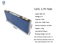
I have a QS138V3 (with gear reduction) motor that I want to use. Controller will likely be a 3shul CL1000 and battery cells something of the prismatic NMC type. I've got my eye on some 72ah CALB NMC cells; hoping for 30S.

The first order of business will be to get all the ICE components removed so it might look something like this (not my photo):
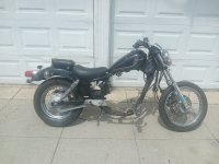
448178040_2345206059164661_9019791358677133096_n.jpg

Life is getting busier than ever so this build may take longer than I'd like but I figured there is no time like now to get started and at least try,
 
Nice bike to convert and ride/cruise on when it's a quiet EV. You already have a mid motor but this bike would have been an ideal candidate for a hub motor.
 
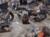
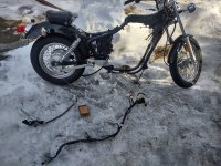
I've managed to get the major ICE components removed. It feels good to get there but now the more challenging work / planning begins.
IMG_20250208_085731055.jpg

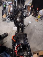
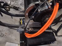
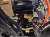
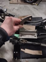
Some mock ups with the motor sitting on the frame:
IMG_20250208_091948440_HDR.jpg


IMG_20250208_092005563.jpg

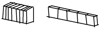
The cardboard represent the battery cells I plan on using. I've still got some more planning to do for this but I want to get the motor mounted first before I can truly know how much space I have for the battery pack.

IMG_20250208_103517412_HDR.jpg

6a453aae4c.png

Nice bike to convert and ride/cruise on when it's a quiet EV. You already have a mid motor but this bike would have been an ideal candidate for a hub motor.
Yes, It would certainly give me more space for a battery but I really wanted to keep the original rear wheel and have the flexibility to change sprokets etc... to suit my riding. I have a build with a QS260 hub but any work on the rear tire or wheel etc... becomes very difficult due to the weight and dropout requirements.
 
Last edited:
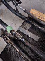
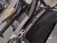
So far, the planning of how and where to secure the motor is kicking my butt. I've already got a stainless steel motor mount that I'd like to use so I will have to add some flat plate to the bike frame. I'm trying to do some calculations and measurements to make sure the sprocket alignment and height is correct.

IMG_20250209_161109581_HDR.jpg
IMG_20250209_162130778_HDR.jpg
IMG_20250210_161833500_HDR.jpg

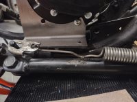
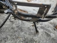
There isn't much room for to move the drive side of the motor outward because of the kickstand support; and I'd like to keep as much of that intact as possible.
IMG_20250210_161841211_HDR.jpg
IMG_20250210_193846649_HDR.jpg

I may end up adding some angle iron to mount this side of the motor to the bike. Unfortunately the motor mount is stainless steel and would require a different shield gas and filler wire to weld to mild steel; not something I want to get into at this point.
 
Can you use heavy channel? ( or have someone with a press brake make some custom out of 12g ) to weld to the frame for a platform for your ss brackets?

A custom bend would let you do a Z, or non-symmetrical flanges. That could be worth the extra cost and trouble.
 
Although it may not look like much; I have bitten the bullet and made my first cut on the bike. I removed a section of round plate that was welded on top of the main frame tubing. As you can see it is there to support the kickstand. I removed only a section to keep the kickstand support intact and in the same position.
IMG_20250215_132241040_HDR.jpg


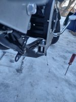
I think cut up some angle iron to create a flat surface for chain-side of the motor mount to sit on. The plan is to weld some nuts under the new plate so the stainless bracket can be bolted on. I'm a bit concerned with getting everything in perfect alignment but I suppose I should be able to get everything mocked up before I weld it up.
IMG_20250215_132305540_HDR.jpg

Can you use heavy channel? ( or have someone with a press brake make some custom out of 12g ) to weld to the frame for a platform for your ss brackets?

A custom bend would let you do a Z, or non-symmetrical flanges. That could be worth the extra cost and trouble.

I suppose the heavy channel would do exactly that; although in this application I only need 2 side of plate and not 3. I guess I will still have to weld in a small strip anyway.

For the non-chain side, the support plate has to go over or under the rear brake cable housing (not sure if that's what you call it in the motorcycle word).

I finally heard back from a supplier on Alibaba to arrange for two sample cells (CATL 72ah NMC) to be purchase so I can stress test them. I'm hoping to be able to hit them with short bursts (a few seconds) of 450A. The datasheet says they can only take 3C bursts but if the DCIR is around 0.6mOhms or less like advertised; they should be about to do it.
 

Attachments

  • CATL 72Ah.pdf
    714.9 KB · Views: 2
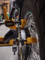
I've been spending a lot of time thinking a fiddling around with the motor; being concerned with all the alignment axis etc...
I first tried to check alignment with a copper pipe; but the pipe was not as straight as some threaded rod I had.

IMG_20250219_191825597_HDR.jpg

IMG_20250219_192210676_HDR.jpg

IMG_20250219_192225161_HDR.jpg

Since I was mostly concerned with getting the sprocket offset correct; I was fairly happy with the alignment and was able to move on to adding the other side of the motor support.

IMG_20250221_194701150.jpg
IMG_20250221_194716857_HDR.jpg

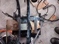
I will be adding some more support for the non-drive side and completing the welds.

The sample battery cells have been ordered but they haven't shipped from the supplier yet; I imagine they will take a long time to get here but I'm willing to wait so I can test the samples before ordering a full pack's worth of cells.
 
I've nearly completed the motor support on the frame but need to finish welding the underside of all the joints. My plan is to put the bike on it's side somehow so I can reach and see better. I tried doing some of the welds while upside down but it wasn't going well.

I also have noticed that the chain is sitting too low and will rub on the chain guard on top the swingarm.
IMG_20250225_183435005_HDR.jpg

My plan to correct this is add some flat plate between where the motor support will bolt to the motor mount. I sat on the passenger seat but the suspension didn't seem to compress enough to make a difference with the chain rubbing; perhaps the extra weigh of the battery pack/other components will make up the dfference?
 
I sat on the passenger seat but the suspension didn't seem to compress enough to make a difference with the chain rubbing; perhaps the extra weigh of the battery pack/other components will make up the dfference?
It might, but consider what might happen if you hit a small bump or pothole: the suspension will shove the swingarm down during the half-second the rear wheel is in the air. And the chain will be moving then... Could be bad. I know this, because it happened to me two days ago: my chain clicked the center stand, but there was always clearance once I was sitting on it, so I assumed it was fine. Two nights ago, I ran over railroad tracks two quickly, and the chain caught at speed and ripped off and twisted around the axle. My fault, and I was fine, but you can be sure I fixed the issue.
 
  • Cheers
Reactions: pwd
It might, but consider what might happen if you hit a small bump or pothole: the suspension will shove the swingarm down during the half-second the rear wheel is in the air. And the chain will be moving then... Could be bad. I know this, because it happened to me two days ago: my chain clicked the center stand, but there was always clearance once I was sitting on it, so I assumed it was fine. Two nights ago, I ran over railroad tracks two quickly, and the chain caught at speed and ripped off and twisted around the axle. My fault, and I was fine, but you can be sure I fixed the issue.
Thanks you for the reply and story. I hadn't considered that yet; I will definitely go for getting the sprocket height corrected to avoid something like that.
 
Do you have a 3d printer? I wonder if it would be possible to print some sort of guide or slide that sits on top of the chain guard to provide a smooth, sacrificial path for the chain. Certainly it will wear out and wear through, but if you have a 3d printer and settle on a design that works for you, I'm sure you could get it down to just a few cents cost per print.
 
Is such a system where the chain is permanently sliding on the swingarm actually feasible? I am in a similar predicament (we'll see how bad after new bigger rear sprocket arrives), but I was under the impression that under normal driving conditions the chain should clear the slider and only touch it with the suspension fully extended.
 
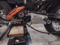
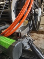
I think I've got a solution to the chain height issue. I added some square tubing between the support and the motor mount to raise the whole motor up:

IMG_20250227_125930563_HDR.jpg
IMG_20250227_125941874_HDR.jpg

Do you have a 3d printer? I wonder if it would be possible to print some sort of guide or slide that sits on top of the chain guard to provide a smooth, sacrificial path for the chain. Certainly it will wear out and wear through, but if you have a 3d printer and settle on a design that works for you, I'm sure you could get it down to just a few cents cost per print.
The bike already has a plastic chain guide for that purpose (I think), you can see it in the new photo just above the foot peg.

Is such a system where the chain is permanently sliding on the swingarm actually feasible? I am in a similar predicament (we'll see how bad after new bigger rear sprocket arrives), but I was under the impression that under normal driving conditions the chain should clear the slider and only touch it with the suspension fully extended.
I can't see how having the chain constantly making contact with the guide would be feasible; it would wear down in short time I imagine.
 
Last edited:
I'm pretty sure on large rear suspension travel bikes it's virtually unavoidable to have the chainline be broken by the top of the swingarm in fully extended position; raising the sprocket higher radically changes the antisquat behavior of the rear suspension and replacing a $15 slider which is a wear item is seen as a reasonable cost.

The sliders are meant to be used only as long as the narrow vertical part is tall enough to allow the rollers to ride on it. Since the rollers can, well, roll, the chain doesn't just slide on the slider with friction. If the chain gets dirty, though, and the rollers start putting more pressure on the slider, then yeah, I guess it would get worn very quickly.

Either way, looks like your new motor position is about perfect.
 
If it's possible, I recommend adding spacer tubes inside the square tube for the bolts to pass thru to prevent any deformation of the square tube over time (which would change your motor position, potentially causing chain tension/alignment/etc issues). The spacer tubes dont have to be fixed in place; the bolts passing thru them do that.
 
Nothing to report visually but I am still waiting on the Alibaba supplier to ship my two sample cells. He says he will provide tracking tomorrow (I really hope).

I've started planning my safety, pre-charge and main power circuits. I have ordered:

500A contactor w 12-24VDC COIL
12V relay that can switch 250VDC
a 230 ohm and 330 ohm 10W resistor for pre-charge (I will see which one works better)

12V delayed ON relay so I can activate the main contactor after X number of seconds when I turn on the 12V step down, allowing the pre-charge circuit to do it's thing

500A 125VDC Fuse

2AWG cable + 2awg cable lugs for battery connections
 
I got a few hours in working on the bike and removed the main wiring harness. My plan is to sell the harness and all the I.C.E. components once the conversion is complete. I'm glad this is a relatively simple motorcycle. :
IMG_20250313_154023620_HDR (1).jpg

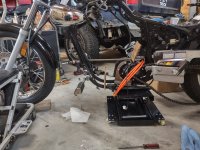
I've completed the welds for the motor mount. I wasn't able to weld the underside initially so I brought the bike outside and tipped it on it's side for easy access. Sure, it may not be pretty but I think the welds should be good enough.
IMG_20250313_175249059_HDR.jpg
IMG_20250313_175253272_HDR (1).jpg

I've also added some aluminum spacers (cut from some aluminum tube I had) inside the square tube as per recommendation from Amberwolf.
IMG_20250313_183934712_HDR (1).jpg

As it sits. The foot brake will bolt back into the normal location.
IMG_20250313_182457073.jpg
 
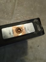
The two sample cells have arrived. Ordered from (had to ask them to weld studs) :

IMG_20250326_183857509.jpg

IMG_20250326_183921283.jpg
My ACIR measurement showed them at 0.71 mOhms at around 19 Celcius - within spec of the advertisement online but a tad higher IR than I had hoped.

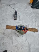
I began testing them using some cable (enough to give me about 7.6 mOhms resistance) submerged in a bucket of water; activated with a contactor.
IMG_20250325_095822709_HDR.jpg

The voltage drop was high compared to what I was expecting from the ACIR measurement, I still have lots to learn about cell testing but figured the cold (cells were probably 10 degrees Celius) may have been contributing to that so I brought the setup indoors.

The load test (I know it's crude) faired slightly better in the warmer environment but still disappointing compared to the ACIR measurement I took. I averaged about 0.996 mOhms of resistance per cell over a course of about 10 tests. The test results look something like this:

Test 1: dropped 3.99V to 3.69V with a current measurement of 286.4A
Test 2: dropped 3.97V to 3.63V with a current measurement of 389.8A
Etc...

I was hoping to test at around 450A but for whatever reason didn't get there (maybe I need a tiny bit less resistance on the load?) but with an average of 0.996 mOhms resistance, I calculate a single cell would sag down 0.4482V at 450A: that is too much in my book.

I'm a bit disheartened by all that voltage sag.

Perhaps there is something wrong with my testing and/or I was expecting too much from this cell?
 
I mean, they specify max current at 348A. What were the temperatures of the cells during and after those tests? Did you measure the time it took to reach e.g. 60 degrees C? I know you mentioned it was cold out but the cell might have heated up internally by some unknown amount.
 
Last edited:
Interesting test, is it the 72Ah model from earlier in the thread? 6c discharge =432A, max peak 10c.
You dont get any swelling when you discharge hard like that? Maybe you could try to put some pressure on it and see if that makes any differense. Also try higher temp, 30-40 degrees c maybe.
 
You dont get any swelling when you discharge hard like that? Maybe you could try to put some pressure on it and see if that makes any differense. Also try higher temp, 30-40 degrees c maybe.
All the prismatic and pouch cells I know of should be compressed in a stack along their largest faces. Some of them have publicly available spec sheets with the psi pressure rating required (or recommended).

Cells that look like (and are internally built like) the ones here in this thread can be found in compressed packs such as this1743131338664.png
This thread has some info and links
 
  • Like
Reactions: pwd
I mean, they specify max current at 348A. What were the temperatures of the cells during and after those tests? Did you measure the time it took to reach e.g. 60 degrees C? I know you mentioned it was cold out but the cell might have heated up internally by some unknown amount.
On the surface, the cells measured about 8 Celsius outside and around 17 Celsius inside. After doing 6x 10 second bursts of around 250A with split second current spikes of ~390A at the start; and about 15 seconds apart; the surface temperature only rose to about 20 Celsius from 17 Celsius.

Interesting test, is it the 72Ah model from earlier in the thread? 6c discharge =432A, max peak 10c.
You dont get any swelling when you discharge hard like that? Maybe you could try to put some pressure on it and see if that makes any differense. Also try higher temp, 30-40 degrees c maybe.

Correct, these cells are supposed to be the 72ah CATL cells. One of the cells has swollen a bit after some testing. Good idea about adding some pressure and increasing the temp.

I ran a bunch more tests; this time with some compression on the cell and an attempt to increase the starting temperature.

Here is my setup - don't pay attention to the voltage drop shown in the photo - the current meter and volt meter don't show peak readings at the same time
ezgif-3239b4c5e3eab1.gif

Started with 21 Celcius and did see an improvement (less voltage sag) - averaging 0.868 mOhms after 6 burst tests
Got the ambient temp up to ~ 24 Celcius and averaged 0.84628 mOhms after 6 burst tests

Example:
Compression Test 1 @ 21 Celsius : dropped 4.01V to 3.67V with a max current measurement of 392A
Compression Test 2 @ 21 Celsius : dropped 4.00V to 3.68V with a max current measurement of 398.8A

Voltage sag would still be a fair amount at 450A, but perhaps 400A peak for a few seconds would still make me smile on this build?

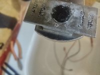
I wanted to make sure everything was tight but then one of the studs sheared off:

Those welds don't look the strongest, and are certainly making me question if these will be up to the task
IMG_20250327_134249752.jpg

IMG_20250327_134217273_HDR.jpg

These are M6 studs for reference:

IMG_20250327_135054198.jpg

You can spot some pitting on the welds here, perhaps making a weaker bond and connection:
IMG_20250327_135048168.jpg

I've read that welded studs added like this are not ideal as the cells are really just meant to have bus bars welded directly to them. I really want to use cells with studs to make my pack build "easier".
 
I have gone down the rabbit hole of looking for more optimal cells for this build and am going with this cell:
12bbc704c781a6e52c463d59ea8459bd.jpg

It's an SVOLT 90ah NMC cell that is half the width but thicker than the original cells I was looking at. This should allow me have two rows side-by side on the bike and a bit more flexibility in terms of cell placement. Based on the datasheet and some test info; these should also have less internal resistance (about 40% less than the original 72ah cell I had tested). The seller has said they will double weld the studs for greater shear strength. You can see this type of stud offers more contact area (maybe double) what the other cell had.
 

Attachments

  • CV01 90Ah 4.35V产品标准.pdf
    858.7 KB · Views: 2
This should allow me have two rows side-by side on the bike
just to be sure, they would be laid out like the first way, not the second? (because they should ahve those large faces in compression)

1743547749782.png
 
Back
Top