BotoXbz said:
A little update on my PSU hacking attempts:
{snip}
Work in progress still, code on GitHub https://github.com/BotoX/huawei-r48xx-esp32
Using this lib for CAN on ESP32 https://github.com/sandeepmistry/arduino-CAN
I want to use the Huawei as a jump-start power supply for a 20kW flow-battery installation using Redflow ZBM-2 zinc-bromide units. I've got them in place, but COVID-19 has sabotaged the commissioning timeline. One of the peculiarities of a flow battery is that they can be (and in fact
need to be for dendrite removal) fully discharged. From that state they need a 56V power supply at high amperage to get them to the point that they can be run normally, and I wanted to set up a Huawei rectifier on the DC bus to kick in if/when required under BMS control - whilst it is possible that the Sunny Island can do this, that is not yet clear.
Because a rectifier is inherently designed to operate in a n+1 environment with high reliability and life, it seemed ideal. But of course the controls are proprietary. I decided to build a CANBus unit in the hope that I could set the voltage and current limit permanently with a view to using the rectifier under BMS control using dry contacts.
Originally I purchased an Arduino UNO and CANBus shield plus a couple of MCP2515 cards (cheap as chips) but actually implementing a CANBus tool from the tools and code out there turned out to be a lot more difficult than I thought. Plenty of mickey-mouse demos which will turn an LED on on a receiver when a transmitter is actuated, but functional transceivers either relied on obsolete and withdrawn software, or were firmly oriented to vehicles, and as this appears to be a lucrative market, pried accordingly.
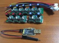
As I also had a an ESPDuino clone I was seduced by BotoXbz's solution. So here are a few errors I made en route: Note that mose ESP32 boards are 3.3V, and do NOT require a CANBus chip - just a driver. I ended up cannibalising an MCP2515 (which is 5V) by stripping the CANBus chip and strapping to the driver. Messy, but cheaper - plus it saved my waiting three weeks for a part.
- Install PlatformIO and let it pull in updates.
Import the huawei-r48xx-esp32 GIT
Edit main.cpp to insert your WiFi SSID and passphrase
Edit platformio.ini to add monitor_speed=115200
The route I took is slightly different - an ESPDuino is an Arduino card with an ESP32 and runs off 5V.
GPIO4 is CRX, GPIO5 is CTX, although different pins can be programmed using CAN.setPins(rx, tx)
If you do cannibalise an MCP2515 I suggest you remove the crystal first, then cut off the pins on the side nearest the crystal as close to the chip as possible to avoid tearing the tracks.then bend the chip up (trying to bend the pins without ripping the pads off) sufficiently to cut the other side.
Now desolder each pin from the pad.
Now strap RXD and CXD to the input pin of your choice. Lizst wire might be good, I used telephone single-strand, which gave me issues with melted insulation on the bends.
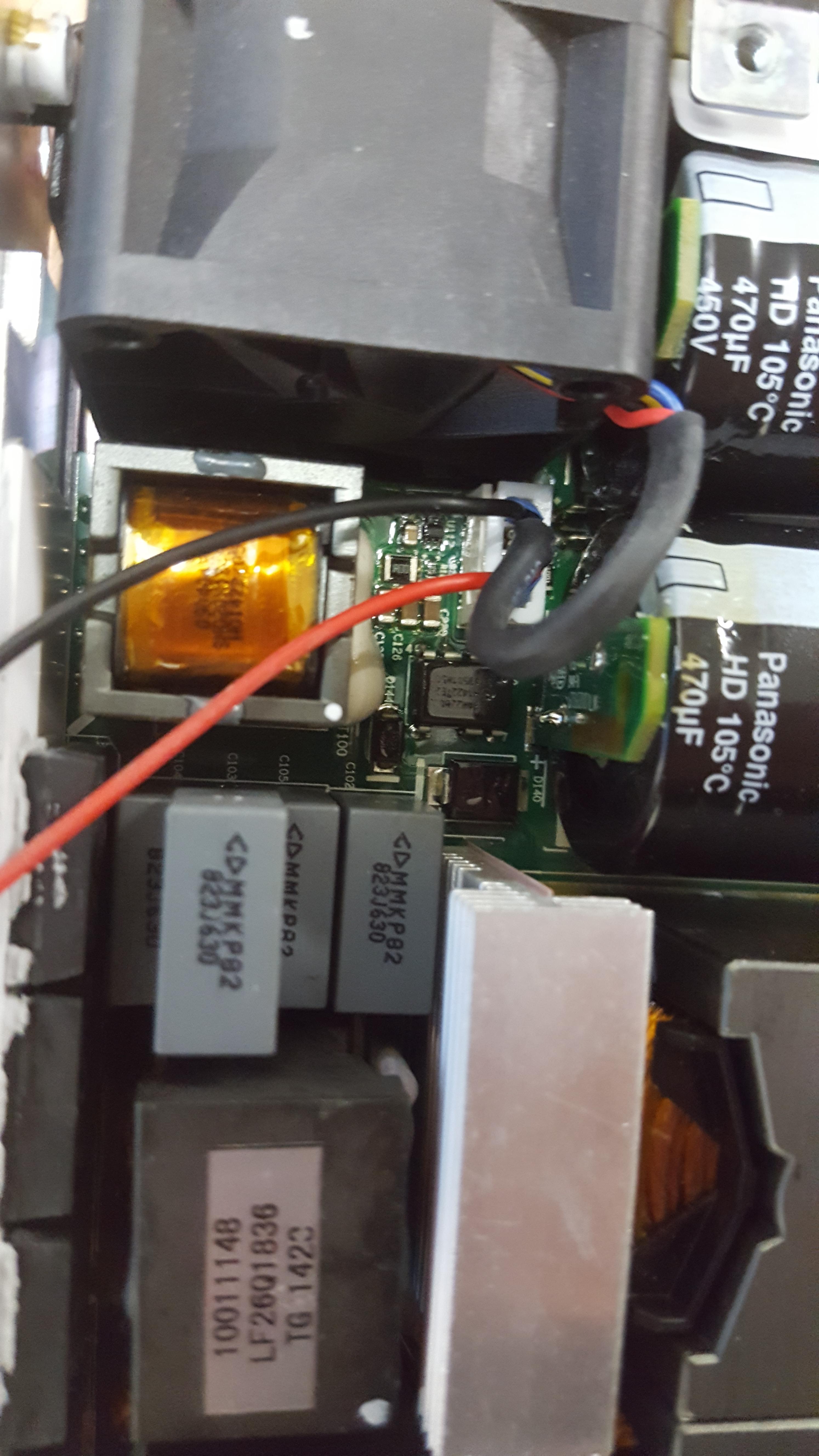
There is a 120 Ohm resistor in the MCP2515 - you need to strap J1 - I then added a terminating 120 Ohm in the cable at the Huawei. You might get away without, but it should eliminate reflections in the cable.
When I first looked at BotoXbz's code I despaired - how did the bits fit into an Arduino code space? The answer is that they don't. I installed PlatformIO, whixch is "Open source, cross-platform IDE and Unified Debugger. Static Code Analyzer and Remote Unit Testing. Multi-platform and Multi-architecture Build System", but the big-ticket items are that it allows the use of multiple types of card, allows a GIT source to be utilised as-is, and provides all the tools you need - for free. I cannot emphasise how gob-smacking it is to use an open-source tool like this - when I was in my first job (in the seventies) I was working with UV-erasable eight-bit processors for a PABX line card, and the hardware and software tools needed were pricey, clumsy and proprietary. This is my first time playing in the software pond since that design (by the way - a lot of engineers thought it insane to have an eight port line card design with nine microprocessors 8) ) and it's a whole new ball-game.
Suffice it to say (and to my complete amazement) the GIT transferred smoothly, the code assembled and transferred, and after a hiccup with swapped CAN-L and CAN-H I was able to talk to the Huawei.

I used a connector, rather than soldering to the edge of the PCB.


")