• Hello ES! We could use some help to get us past the finish line on building the new knowledgebase for the forum.
    Can you donate? Please see our fundraising page. Thank you!

Single/Side Shaft Hub Motor Build/Modify

Mihai_F

⚡ Regular
Joined
Oct 11, 2021
Messages
236
Hello everyone and happy new year, with amazing builds and adventures!
So here it begins with an new thought, i'm interested in modifying two e-bike hub motors or hub outrunners from hoverboards or else, to have an single side thick and sturdy shaft, and have them installed with a 20" rims, on the front end on my trike for 3. The power level needed is about 350 to 500W (each) and has to be low speed and with good torque.
Before i embark in this project, i ask you if any one has done this single side shaft conversion to a hub motor before, or if there is this kind of motor out there and does NOT cost 1000$, i found such motors out there and are insanely expensive.
The cost part is sensitive on this project :mrgreen:
 
Last edited:
That is cool motor, unfortunately here across the pond, in the land of "unoptanium"(europe), such good stuff is not available. Although they do export it, but upon import in my country i'l be ripped with taxes for two of those 😅, and that is way out my budget.
So the alternative, i found two used hoverboard 6,5" motors on the net, at e bargain price (20 euro), they have 16mm single side shaft and about 350w. The plan is to remove the tires, and then see how can i add flanges or drill the spoke holse in the existing flanges, and then add an adapter flange for the disk brake, so it is all about flanges 🤪, i'l come back with photos soon.
 
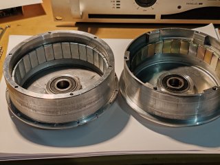
I had cut of the tires of the motors, the outer flange is thick and big enough to drill holes for the spokes, the inner one unfortunately is not thick enough, it has some empty spaces (lightening holes) in the thickness, and it does not seal the motor any more since there is no tire any more to cover the empty spaces. So i believe the inner flange i will make a new one and also maybe have the disk mount in it, made in a single piece. Also disassembled one motor so i can "reverse engineer" the winding, it is wound with 3 parallel strands of 0.5mm copper wire (Y terminated), KV is about 20.7rpm/volt, and that might be a bit of an issue when wheel diameter increases from 165mm to 540mm, for ex: at 830rpm (40V) 165mm the wheel speed is 25km/h, but at 540mm(20"rims) the wheel speed is 84km/h for same rpm. So a rewind with a KV of about 10rpm/volt might be more suitable for my low speed high torque application, but will see.
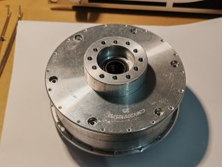
here are some photos of the motors so far.
1000052913.jpg1000052915.jpg1000052916.jpg1000052918.jpg
 
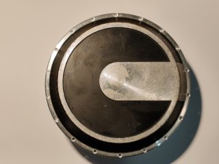
Back with updates, i swapped the motors, found older versions that are more powerful and have solid flanges and rotor can.
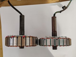
The first ones had 18mm stator length and winded with 3 x 0,5mm strands , the ones that i got now have 23mm stator length and winded with 4 x 0,5mm strands, and magnets longer also.
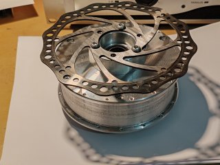
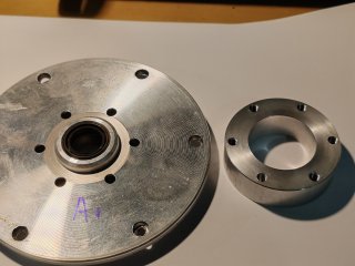
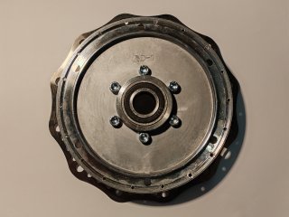
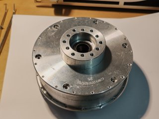
I made the disk flanges with both 44 and 47,5mm bolt pattern, also turned the motor flanges in order to center the disk flange. Made a pattern for 18 holes, transferd punched it to flanges and drilled all the spoke holes, 36 per motor, with 2,5mm drill, and countersunk with 4,5mmdrill to match the J spokes ends.
Calculated the spoke lengths, 134mm spokes are needed.
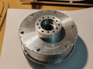
here are some photos:
1000054254.jpg1000054252.jpg1000054248.jpg
1000054246-jpg.383780
1000054245.jpg1000054242.jpg1000054244.jpg
 

Attachments

  • 1000054246.jpg
    1000054246.jpg
    3.1 MB · Views: 32
  • 1000054254.jpg
    1000054254.jpg
    3.4 MB · Views: 0
  • 1000054254.jpg
    1000054254.jpg
    3.4 MB · Views: 0
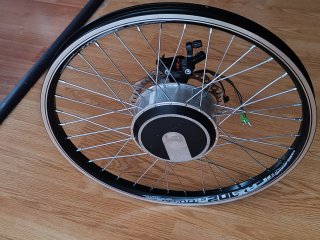
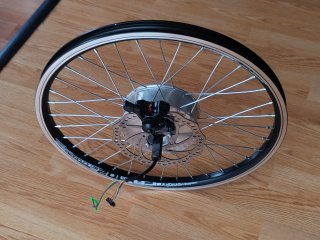
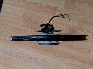
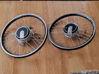
Parts came in, rims and spokes, laced and trued the wheels, all is nice and good. Now comes the next part, making the attaching clamp/bracket for the wheel shafts to the steering spindles, but that will be moved to the trike for 3 topic.
here are some photos.
1000054468.jpg1000054470.jpg1000054469.jpg1000054473.jpg
 
Back
Top