• Hello ES! We could use some help to get us past the finish line on building the new knowledgebase for the forum.
    Can you donate? Please see our fundraising page. Thank you!

Sur-Ron - New Mid drive Bike

Hi,I did not sniff the communication, but my friend do. I planning to connect to it via arduino, and print on LCD :current,cell voltages, temperatures, etc. BMS can be also reconfigured, my friend has config files where he can do changes and then send it to BMS. He increased current limit in my battery from 95A to 125A. So my BMS is fully working and its safer than bypass and still fully working coulomb meter (percentage LCD) :D. I did shunt mod to my controller so i needed to modify battery for bigger current.
 
That's interesting, do you think you could find out what message needs to be sent to request basic info from The BMS?
 
stepus said:
I finally made that video about shunting the controller :D
[youtube]kjQT7CpUh-M[/youtube]
and some hi quality photos :

So would it not be easier to just replace the magnets with either a smaller or larger gap. once we have that info everyone can do it. Right now it would be pretty tough for most of us to move them to the right place.
 
Hi, its not magnets, its iron core to "catch" magnetic field aroud terminal, and direct it through hall sensor. And yes, it will be easier to find similiar material ring, and cut in it larger gap - then i thing it dont need calibration like i do. But we still dont know if stock controller is 24fet like mine was, or its 36fet - so it can be modifed to currents i have.
Controller didnt blow up yet :D, so i thing 125A is OK for it.
 
MOTOR Detective! :twisted:
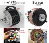
After i watched a video from "Electrified clahllenge" that was showing the magnet replacement on a Motenergy ME1718 I found that this motor was pretty similar to the Sur ron motor in many way! https://www.youtube.com/watch?v=C3vieYw6rBc&t=84s

Motenergy were making various motor for Zero motorcycle and i know that there are some varient of the 75-7 motor like the ME1507 and that it is the same factory that were making both if i remember correctly.

Maybe Motenergy could also be the Sur ron manufacture? Both ME1718 have the same number of poles, same rotor design, very similar stator design and motor extruded casing....

So maybe for these that run it accidently at 14krpm and have magnets flying appart you can get magnet from motenergy.
sur ron compare to me1718.jpg
 
Depending on the diameter, maybe it would be possible to make a liquid cooled version of the Sur ron better for the BAC8000 72V users.!

I contacted Motenergy to know about possibility to buy parts.

Maybe it is also possible to use the ME1718 instead of the stock motor. remember that the sur ron motor has spacers to fit in the frame. maybe there is enough room for that :wink: The ME1718 has more stator and rotor width. Taking the Sur ron motor side covers and fiting these to the ME1718 stator as well as modifying the shaft to match the sur ron pulley... it could work ? :)

Doc
 
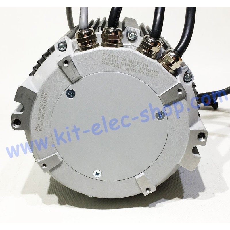
similar mounting holes too: https://www.kit-elec-shop.com/17817-large_default/synchronous-motor-me1718-pmsm-brushless-ip65-6kw-sin-cos.jpg

synchronous-motor-me1718-pmsm-brushless-ip65-6kw-sin-cos.jpg
 
Me1718 specs:

https://www.kit-elec-shop.com/gb/sy...r-me1718-pmsm-brushless-ip65-6kw-sin-cos.html

Its nominal power is 6 kW for a nominal speed of 4000 rpm.
This ME 1718 motor is a brushless motor, so it doesn't need any maintenance, it is also called PMSM brushless.
It is a three-phase permanent magnet synchronous motor with axial air gap.
The ME1718 motor has an efficiency of 88% for DC voltages between 36V and 60V DC.
It is a 5-pole (10 magnets) motor.
The direct current is 120 amps for a voltage of 60V DC.
Its permanent output power is 6 kW at a voltage of 60 VDC.
The maximum rotor speed is 5500 rpm.
The winding has xx turns per phase.
Its resistance between phases is between 5.06 and 5.28 milli Ohms.
The inductance between phases measured at 1000 Hz is between 39 and 43.5 micro Henry.
Its mass is 13 kg.
It has a temperature sensor equivalent to KTY84-130 and a sin/cos type position encoder.
This ME1718 motor is waterproof and is IP65.
Explanations of the terms CW (ClockWise): clockwise and CCW (Counter ClockWise): counterclockwise.


IMPORTANT The ME1718 is the Sin/COS version and the ME1719 is the UVW ( hall sensor version)


Direct Manufacture: http://en.jintankm.com/intro/32.html

Motor dimensions: https://www.kit-elec-shop.com/gb/index.php?controller=attachment&id_attachment=787
Motor performance curves: https://www.kit-elec-shop.com/gb/index.php?controller=attachment&id_attachment=788


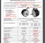
motor supplier confirmed to be Jintan.PNG


One of the supplier: https://www.miromax.lt/en/m-6/c-39/...ali_power_48kw72kw____64ag97ag___240cm3360cm3
 

Attachments

  • me1718 and 1719 full spec.PNG
    me1718 and 1719 full spec.PNG
    96.5 KB · Views: 3,240
STOCK 2021 MOTOR MEASURED SPECS:
As many of us are overpowering their motor " a bit" it is great to have a baseline as a REFERENCE of a brand new unaffected motor
Motor is new ( 87km on it on stock batt and controller:
Use these as a baseline to compare your motor if you suspect that you might have toasted it (i did not said ROASTED!😂) or if you find any performance loss.

Inductance and DC resistance:
Measuring these is a good way to know if the winding is burned or damaged. NOTE: the rotor position affect a bit this value so the best way is to measure the minimum and maximum and mage the average. Also these value will not be the same is your rotor is not present in the stator.

Magnet strengh:
If your motor had torque loss and spin faster(at no load) it might be that your magnets goes pass the Curi point (permament magnetic loss)

Date: 2 August 2021:

2021 motor version
p/n:11100-YQ2A-0201

Magnet strengh:
4200 +/-50 Gauss max

Motor DC resistance:

U-V 9.290 miliohms
V-W 9.509 miliohm
W-U 9.429 miliohms

Motor inductance:

U-V min:43 max:51 avg: 47uH
V-W min:44 max:52 avg: 48uH
W-U min:43 max:51 avg: 47uH

-------------------------------


Date: 2 August 2021:

**** 2018 old motor ****:
p/n:11100-YQ2A-0200

Magnet strengh:
N/A ( not measured yet )

Motor DC resistance:

U-V 10.385 miliohms
V-W 10.637 miliohm
W-U 10.228 miliohms

Motor inductance:

U-V min:47 max:56 avg: 51.5uH
V-W min:48 max:55 avg: 51.5uH
W-U min:47 max:55 avg: 51uH

-------------------------------


Doc
 
stepus said:
Hi,I did not sniff the communication, but my friend do. I planning to connect to it via arduino, and print on LCD :current,cell voltages, temperatures, etc. BMS can be also reconfigured, my friend has config files where he can do changes and then send it to BMS. He increased current limit in my battery from 95A to 125A. So my BMS is fully working and its safer than bypass and still fully working coulomb meter (percentage LCD) :D. I did shunt mod to my controller so i needed to modify battery for bigger current.
PLEASE tell us how this can be done. Would be amazing to be able to re-program the bms instead of blindly bypassing it!!!


Sent from my iPhone using Tapatalk Pro
 
Nice find DOC !

My friend has a SW and RS485 converter from sur-ron as a service man, so he did some digging into config files they give to him with some FW for repairing some BMSs, and findout it can be fully customisable. Reading BMS is possible with every RS485 converter, but writting config is possible only with RS485 converter from surron. Config files are worthless without original RS485 converter from sur-ron.
I thing its not worth it to modify stock battery, everyone buys a new battery 72V anyway, because 60V surron battery is a piece of crap, mine sags from 65V to 55V at 125A :D Balancing cells is also to laugh. So if you want a real power you need a different battery.
I did a shunt mod to controller, and modify battery just to try it :D and do bike a little more funny. In a future i going to buy also 72V battery and mod surron controller for it or i will do my own, or buy some :D
 
Absolutely, new batteries are gonna be better, but for those of us who have stock 60v, we would still like to get max performance out of them. I'd be willing to pay a small fee for someone to reprogram my 2 batteries. Once they die I'll get something better but might as well run them till they quit.
 
stepus said:
Nice find DOC !

My friend has a SW and RS485 converter from sur-ron as a service man, so he did some digging into config files they give to him with some FW for repairing some BMSs, and findout it can be fully customisable. Reading BMS is possible with every RS485 converter, but writting config is possible only with RS485 converter from surron. Config files are worthless without original RS485 converter from sur-ron.
I thing its not worth it to modify stock battery, everyone buys a new battery 72V anyway, because 60V surron battery is a piece of crap, mine sags from 65V to 55V at 125A :D Balancing cells is also to laugh. So if you want a real power you need a different battery.
I did a shunt mod to controller, and modify battery just to try it :D and do bike a little more funny. In a future i going to buy also 72V battery and mod surron controller for it or i will do my own, or buy some :D

I would love to know more about this! There was always something that didn't sit well with me regarding a physical bypass of the BMS.

What is so special about the Sur-ron RS485 cable? Can we get some photos or details on it? If we had a config file and the details of the cable we may be able to homebrew a solution to avoid physical bypass.
 
Hi, my friend has the 485 surron converter and can modify config on some FW versions of the batteries, not me. I just plan to connect to 485 and read the data from the BMS and display it on the screen on handlebar. It will show voltage,current, temp, power, calculated consuption and range etc. Also i thing it could convert ANT BMS data to surron data format, so on l1e version surron there will not blinking error and showing SOC and voltage from aftermarket battery.

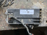
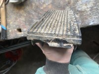
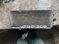
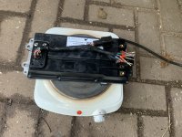
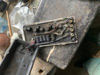
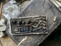
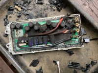
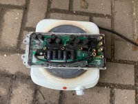
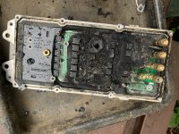
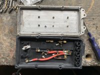
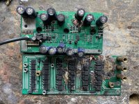
Meanwhile my friend sent me blowned old surron controller, so i deppoted it :D
It looks similar to newer FOC that i deppoted and tuned :D
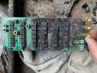
Current sensing is on Batt - and with shunt 1mOhm. There is none phase current sensing - they probably limits PWM duty cycle by RPMs.
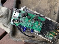
Current sense opamp is TL3472C - shunts are four 4mOhm 1% resistors in paralel
MCU is CY8C24533, driving three IR2101s boosted with transistors
Fets are same as in my newer FOC controller - IPB042N10N3

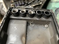
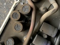
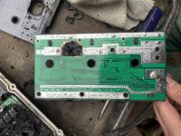
Surron made some progress on the controllers, FOC is better, sensing phase current - safer, gatedriving is on same board as fets in FOC + overall better gate driving, decoupling electrolytes all paralel (on this old controler is 6 electrolytes on battery side, and 8 electrolytes after shunt resistor paralel to fets.

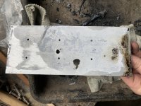
Controller probably fails at phase B high side fets and phase C lower fets, Then an arc ignited through the inductance of the motor, and starts boiling aluminium PCB and even aluminium case/heatsink :D

I will probably use controller case for my controler, probably VESC or Lebowski brain based ? What will you recommend to me ? Best if I could use a already made brain PCB, and built only my own powerstage.
Thanks
 

Attachments

  • IMG_2045.jpg
    IMG_2045.jpg
    538.3 KB · Views: 2,740
  • IMG_2046.jpg
    IMG_2046.jpg
    324 KB · Views: 2,739
  • IMG_2048.jpg
    IMG_2048.jpg
    487.8 KB · Views: 2,739
  • IMG_2049.jpg
    IMG_2049.jpg
    431.5 KB · Views: 2,740
  • IMG_2050.jpg
    IMG_2050.jpg
    515 KB · Views: 2,740
  • IMG_2052.jpg
    IMG_2052.jpg
    591.4 KB · Views: 2,740
  • IMG_2054.jpg
    IMG_2054.jpg
    359.6 KB · Views: 2,739
  • IMG_2055.jpg
    IMG_2055.jpg
    308.9 KB · Views: 2,738
  • IMG_2056.jpg
    IMG_2056.jpg
    661.8 KB · Views: 2,738
  • IMG_2057.jpg
    IMG_2057.jpg
    487.5 KB · Views: 2,738
  • IMG_2059.jpg
    IMG_2059.jpg
    690.6 KB · Views: 2,738
  • IMG_2060.jpg
    IMG_2060.jpg
    491.7 KB · Views: 2,738
  • IMG_2061.jpg
    IMG_2061.jpg
    620.7 KB · Views: 2,739
  • IMG_2064.jpg
    IMG_2064.jpg
    657.9 KB · Views: 2,739
  • IMG_2065.jpg
    IMG_2065.jpg
    472.7 KB · Views: 2,739
  • IMG_2066.jpg
    IMG_2066.jpg
    529 KB · Views: 2,739
  • IMG_2067.jpg
    IMG_2067.jpg
    801.4 KB · Views: 2,741
stepus said:
Hi, my friend has the 485 surron converter and can modify config on some FW versions of the batteries, not me.

Is he willing to provide any details? Like a photo of the cable or its control board?
 
I guess the circuit breaker is sort of useless.
Bet it smells pretty bad.

It would be nice to know what the operating conditions were at the time of failure.
 
For those who are looking to replace the motor KTY84-130 temp sensor inside the motor, be aware that these are discontinued and also that there is alot of fake one on the market that might at a certain high temperature begin to give false reading making that you think your motor was rising temp and now suddenly cool down.. but it is still climbing!

I am now looking to find the exact same replacement thermistor.. Nor Digikey, Mouser or Newark seem to have these.

Doc
 
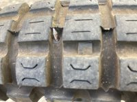
I was out for a ride yesterday and my tire got nailed. Handling started feeling squirrely and I looked down to see the rear tire was going flat. Luckily I was only a few blocks from home and I just walked the bike. The tire side walls are almost stiff enough you could ride it, but I didn't want to totally screw up the rims. Walking was no problem, but embarrassing. The nail went in head first.

IMG_2064.JPG

IMG_2065.JPG
 
Sealant?

I've had multiple larger thorns (1/10"-1/8") that stans sealed up fine but I do understand nail ≠ thorn... for one the thorns break off
 
stepus said:
Also i thing it could convert ANT BMS data to surron data format, so on l1e version surron there will not blinking error and showing SOC and voltage from aftermarket battery.
This would be a really neat functionality for the Surron community. I hope you can figure it out!!
Doctorbass said:
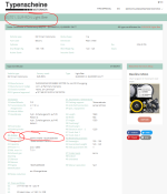
I also found the FULL DOCUMENT ABOUT TUV certification for the Sur ron!!!
Nice! Thanks for all your research and sharing Doc.
 
What is the proper tire pressure for offroad riding with stock wheels?
The manual states 225 kpa (2.25bar) which obviously is too high.
 
Back
Top