Switch mode supply mod

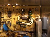
You'd have to snip or modify the OVP zener (the one hiding under the transformer). I added another zener in series with mine so the function still works, only at a higher cutoff. I think I got mine up to about 62v. Going from 62v to 65v shouldn't involve anything major, but you will be stressing some of the components to the limit. I haven't checked what the rating on the output diodes is, that could be a limitation. Going over the voltage rating on the caps by a few volts shouldn't be a big deal, but will shorten their life.

Running at reduced power levels can help compensate for running the voltage higher. Heat is one of the major issues when you over volt these things.
 
Which one is the output diode? I've already snipped OVP zener diode because it just wouldn't go over 54V, so with that removed it now goes up to 59V with stock pot. Output caps are cheap, so I could replace them for higher voltage ones, but after looking at S-350-27 schematics I'm none the wiser what else "sees" output voltage.

I've never run mine at more than ~300W (57.4V@5.5A), but even at those power levels it stayed almost completely cold. Of course, the fan is running all the time.
 
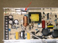
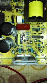
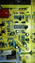
Here's a picutre of my clone S-350-48 supply. The arrow is pointing to the output diode. I don't remember what the part number is on that, and the clamping bar would need to be removed to read it.Output diode.jpg

If you have one apart and can read the number, we can look it up. I'll probably be digging into one of mine soon and could check it out.
 
That was the diode I destroyed when I zapped the NES 350 those months back.
P/n on the dead one was PA905C4

Replaced it with a 30CPF06
Seem to remember they were high voltage


600 volt 30 amp
 
So output diode will handle rised output voltage, right?
 
Nice. When I modify it I'll post results here.
 
two years ago i modified 2 S350-48 for charging my 24S lipo setup.

I recently got four 200-24 meanwells which i also want to cranck up to 10A instead of 8.4.
But if i look at it i don't see which resistor i have to change.
Does anybody has some experience in modifying this model ?

MW200-24.jpg
 
YOU seem to be wanting to do the reverse of what the rest of us do to the Meanwells...we all tend to REDUCE the output current, so we do not burn them out, not icnrease the currents
 
Hi All,

Have read through this entire thread and understand in principle what I need to do but need some assistance identifying the correct areas to modify.

I have acquired a MW s350 48 clone. I intend to use it to bulk charge 12s lipo. The voltage adjustment on the stock unit is fine and needs no adjustment.

So I need to do the fan mod. Is bridging the collector and emitter on q5 the preferred option. My understanding it that this will cause the fan to constantly run keeping the unit cooler and avoid current spikes when the fan kicks in. It will still leave in tack the secondary protection of shutting down the supply if the fan failed and the unit became too hot?

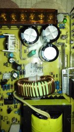
I will then need to reduce the current down to the rated level. I have looked at the board, am I correct that that is a shunt at J3 next to the donut coil? I had to dig away some white goop to uncover it. If so that would suggest the R33 style mod is possible on this. I have found R33 and measured it at 550ohm. R37 is unpopulated but the is no svr2 or space for it. Is R33 the correct resistor to modify for this board?

The 16 pin IC has the following markings: KA7500BD H550TT.

Thanks in advance for your help,

Duncan
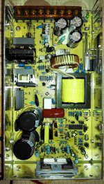
MW-s350-48-full.jpgShunt.jpgMW-s350-48a.jpgMW-s350-48.jpg
 
Oh god, sorry but I really cant remember.

When hacking these was in full swing there were no other options.

I built 3 or 4 of them, but now I'd just go to BMS Battery or similar and order one ready made at the spec I wanted.

Maybe search my other threads, look for one where I built a unit with two Meanwelks in a Dewalt tool case. There may be more pointers on that thread

Sorry I cant help more,
 
If it has a standard wire shunt, then one way to reduce current is to file the shunt, just a tiny bit each time until the max current is down to what you want it at.

Or if you wish to be more precise with the adjustments (and be able to go back up easily) you can measure the voltage across the resistors near the shunt, and see which one(s) go up or down as the current changes while you change the load on it. Then you can replace one of those with a potentiometer, preset to the same value as the resistor, and then vary it slightly to see what effect it has on the current, until you get it where you want it.


But before you do any of these, I would first test the unit to be sure it isn't a hiccup-type unit, meaning that when it goes into current-limiting, it shutsdown the output entirely, then turns back on to see if the "short" has cleared, when it hasn't it shutsdown again, and repeats this cycle at some rate. If it is this type, then it doesn't work for charging batteries unless you also add a current-limiter (like Fechter's) to it, or put it in series with another PSU that *does* do current-limiting the way you want (like a lab PSU).
 
I think I do have someb spare Fechter current limit boards.. need ti check. not sure which revision though.
Send me a PM to remind me if you want one
 
NeilP said:
I think I do have someb spare Fechter current limit boards.. need ti check. not sure which revision though.
Send me a PM to remind me if you want one

Thanks Neil, will bear that in mind depending how it goes over the next few days.

Duncan
 
amberwolf said:
I would first test the unit to be sure it isn't a hiccup-type unit, meaning that when it goes into current-limiting, it shutsdown the output entirely, then turns back on to see if the "short" has cleared, when it hasn't it shutsdown again, and repeats this cycle at some rate. If it is this type, then it doesn't work for charging batteries unless you also add a current-limiter (like Fechter's) to it, or put it in series with another PSU that *does* do current-limiting the way you want (like a lab PSU).

I will check this first on the unmodified unit, I just need to finish the pack harness first!

amberwolf said:
If it has a standard wire shunt, then one way to reduce current is to file the shunt, just a tiny bit each time until the max current is down to what you want it at.

What I think is a shunt is very close to the board so not sure that will be too easy. Also seems a little too permanent.


amberwolf said:
Or if you wish to be more precise with the adjustments (and be able to go back up easily) you can measure the voltage across the resistors near the shunt, and see which one(s) go up or down as the current changes while you change the load on it. Then you can replace one of those with a potentiometer, preset to the same value as the resistor, and then vary it slightly to see what effect it has on the current, until you get it where you want it.
I have removed the board and looked at the traces. R33 and R37 (unpopulated) come off pin 15 of KA7500BD IC. From looking at a schematic that pin looks like a negative input to a error amplifier. The track then goes all the way down to the part I believe is a shunt. Does this seem reasonable?


Duncan
 
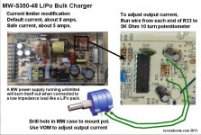
I think you can just hang a pot across R33. Looks the same as the one in the pic below. In your picture, R33 is populated.

From the archives:
mw_s-350-48_limit pot.jpg
 
no idea if any use, and please don't reply to the post linked to below, a good chance I won't remember anyway

but maybe useful info

https://endless-sphere.com/forums/viewtopic.php?f=6&t=35138&hilit=+meanwell
 
NeilP said:
no idea if any use, and please don't reply to the post linked to below, a good chance I won't remember anyway

but maybe useful info

https://endless-sphere.com/forums/viewtopic.php?f=6&t=35138&hilit=+meanwell

Thanks Neil,

The pic of the traces was useful. I believe that the R33 will work and that my board simply doesn't have the svr2 space. The tracks lead to the same pin. So will finish the loom and then test for hiccup mode and all being well try r33 and try to keep the magic smoke at bay!

Duncan
 
fechter said:
I think you can just hang a pot across R33. Looks the same as the one in the pic below. In your picture, R33 is populated.

From the archives:
Yes, R33 is populated, R37 is not and there is no svr2 on the screen. But on the rear r33 and r37 both hit the same traces on either side so fingers crossed that should do the trick.

Thanks

Duncan
 
DuncanS said:
NeilP said:
no idea if any use, and please don't reply to the post linked to below, a good chance I won't remember anyway

but maybe useful info

https://endless-sphere.com/forums/viewtopic.php?f=6&t=35138&hilit=+meanwell

Thanks Neil,

The pic of the traces was useful. I believe that the R33 will work and that my board simply doesn't have the svr2 space. The tracks lead to the same pin. So will finish the loom and then test for hiccup mode and all being well try r33 and try to keep the magic smoke at bay!

Duncan
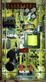
So, finished harness and gave it a spin. Unmodified it was out putting 12.69A and running at about 600W. No sign of a hiccup mode. So I hooked up a pot and retried. Stupidly I only had a 50k to hand and may have turned it the wrong way as there was a flash and the fuse blew. The 2 power transistors at the back of the case have shorted. Shown by red arrows in picture.

MW-s350-48-full transistor.jpg

They have the following markings P 2SC3320 5N. I am trying to find some of these in Egypt but not having much luck. Is there an equivalent or alternative part? The easiest place for me to get stuff from is the following shop:
http://ram-e-shop.com/oscmax/catalog/index.php?cPath=25&osCsid=07c2eac40cb78fca53050e1be771dd51

They don't seem to have the exact part and was wondering if anyone knew of a suitable alternative available from them.

Thanks

Duncan
 
can't help with the transistors I am afraid...

I forgot to look in my box of bits for the Fecther limiter board... I kept walking to that area of my shed and getting distracted..was there all day yesterday doing some lathe repair work.
Will go down there now to look.
 
OK, yes I have got it...version 4.2.6 bored, unpopulated but with all the bits here...looks like I bought enough parts for 5 boards...but only bought there boards..two are used...

will go through the schematic and parts list and make up a pack for you ..

only have instructions for 4.2.5a..... maybe Fechter has a 4.2.6 assembly pdf? if there is any difference?


Anyone care to chip in as to what it is worth with all the part , un assembled?
 

Attachments

  • MW Charge Controller Assembly-Test Instructions-v4.2.5a.pdf
    947.1 KB · Views: 57
OK, gone through the bag of parts and yes a complete set of parts to build the board.
 
I'll check when I get a chance. I don't have those files with me now.

I'm sure there are substitute transistors that can work. I'll look for those when I get time too.

Edit:

I had to look up those files. There is not much difference between those, but I'll have to look closer to see what the difference was. That's going waaay back and I don't remember all the details. I have a set of instructions called 4.2.5b but not 4.2.6. These were the really complicated ones with HVC interface and end of charge cutoff of sorts.

The transistor is NPN bipolar rated:
Collector to Base Voltage VCBO 500 V
Collector to Emitter Voltage VCEO 400 V
Collector to Emitter Voltage VCEO(SUS) 400 V
Emitter to Base Voltage VEBO 7.0 V
Collector Current - Continuous IC 15.0 A
Base Current IB 5.0 A
Collector Power Dissipation PD 80.0 W
Junction Temperature Tj 150 ℃
 
I looked at Ram Electronics in the link. They do not have any suitable replacement transistors. Sorry.
 
Back
Top