Buk___ said:
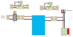
I have a 30A full bridge rectifier somewhere in my "maybe useful someday" box of bits. If I wired that in front of the cheap wattmeter I could strap an led across the input to tell me which direction. And a cheap buck converter could supply power.
You can test this to verify, but since the current has to pass thru the meter shunt unchanged to get to the motor and do it's work (or back from the motor to the controller to charge the battery), you can't use the rectifier because it diverts the current and alters it; it doesn't let it do the work it needs to in the form it started as.
Of course what I really want is a unit that will not only measure, but also log and accumulate. Pretty much what the CA does I suppose; and I might be tempted if I didn't have to shell out again to purchase the logging ability.
Well, the CA does total up the Ah, Wh, A, min volts, etc. and remember these things even when power is lost. It also has a serial output to send the moment-by-moment readings to anything that reads and logs serial data (laptop, arduino, PIC, etc), then you can do whatever you want with that data later.
I don't know of any of the cheap meters that do any of those things. Some of the cheap ones that are powered separately won't lose the data when you turn the bike off as long as the power to the meter is left on, but I haven't seen one that remembers it's data with no power at all (like the CA does).
At this point I'm more tempted by the idea of connecting a precision shunt to a 16bit ADC and Raspberry PI. That'd give me all the logging I would ever need and the ability to attach different sensors to the ADC for measuring other stuff also.
It would; might be a bit of work to get it all working glitch-free.

The idea of instrumenting the phase wires was to allow me to try and work out exactly what the mysterious C13 setting on my controller is actually doing. Is it just as casainho thinks, just a limit to the number of amps the controller will feed back to the battery; or as I guess -- based on your description above -- also a way of telling the controller to feed some reverse current to the motor to increase the braking affect.
An oscilloscope could show you the phase waveforms (a 3+ channel would be best so you can monitor all three at once, but a 2-channel lets you monitor two phases which is the same as what most of the phase-current-sensing controllers would do anyway), which would probably be more useful than current measurements, just because you can instantly visually see what's happening. (though I cant' at the moment remember how you'd set it up to always trigger the display sync so you could easily see which way current was flowing, based on the positive / negative voltages shown).
However, one way to distinguish the two kinds of braking is that the regen can't, by it's nature, go down to zero speed, and it's braking force will diminish as speed drops.
The "EABS" active braking *can* go down to zero speed, and actually hold the wheel against rotation at a stop, and it's braking force does not (or at least should not) diminish as speed drops--it could in fact become greater (because it does not have the mtoor's BEMF to fight against).
A simple test with the wheel off ground (bike upside down, for instance) can distinguish between the two modes. Hold the ebrake lever engaged, then attempt to hand-spin the wheel. If it feels like it is cogging/resisting even when very slowly spinning it, you have active braking. If you have to spin it fairly fast to feel resistance, you probably only have regen braking (or a crippled version of EABS).
The same test on-road may not give noticeable results, because the controller's low-speed or zero-speed braking might be intentionally limited to prevent battery wastage at a stop, if you were holding the ebrake lever even though you have your feet on the ground there'd be no need for the motor to hold the bike still. So the weight of you and the bike against the rolling resistance it does have might still easily roll the wheel, whereas just your hand on the wheel off-ground is a lot less force and might not roll it at all.
There are tricks (FETs shorting the windings momentarily during a cycle, to get the flyback effect, for instance) a controller can use with just regen to make it happen at lower speeds, but there's just not enough current flow or voltage at really low speeds to make those tricks work with just regen. And at zero speed it doesn't work at all, so the zero-speed offground test should easily distinguish between the modes.
The shorting the windings trick *can* be used to get some resistance at zero speed, but it means the energy is wasted, so there won't be any current back to the battery.
The same is true of the EABS modes; if you get charging current from controller battery connection back to the battery, then it's using regen, and not EABS, at the moment that current shows up.
But you need an ammeter or wattmeter to see that; your existing system doesn't read current flow from controller to battery (only the other way round) with no way to reverse it (short of hacking into the controller guts).
The offground handspin-wheel test needs no instrumentation.

My original (probably woolly) thinking was "work out what speed and power is needed to spin the wheel to generate a 1C charging current" and then find a small RC gas motor, attach a suitably sized mandrel, and fix it to a rotating rack stand with a big spring. Set in motion and eat lunch. Simple

I hadn't considered the complication of the black box that is the controller.
It's really annoying when stuff like that gets in the way of something that ought to be really simple.

The alternative is that I get a 3-phase rectifier chip, some caps (and maybe a coil?) and some kind of current limiting circuit and bypass the controller; probably feeding the power back to the battery via the charging connection.
But since I know just enough about electronics to be dangerous; have no idea what that "current limiting circuit" would entail; and have never worked with high current DC; I'll save my rainy day notions for another rainy day

Basically what current limiting does is sense the current via a shunt, and then it begins lowering the voltage as current gets too high, so that the voltage difference between the charger output and the battery are low enough at the resistance the battery is at at that moment, that the current drops to the level the limiter is set at. It increases voltage if the current drops too low, up to whatever the max voltage the system is limited to (so you don't overcharge either).
Chargers do this via PWMing FETs just like motor control, etc., by chopping the voltage into pulses that *average* the voltage you want to get the current you want (and then smooth that with capacitors/inductors), but you could do it with a throttle control on the RC ICE driving the motor, since the faster the motor spins the higher the voltage, and vice-versa. Have the current sensor drive an RC servomotor based on the current limit.
To do it via PWM you'd have to build a FET circuit, etc., and that's more complicated (if things go wrong FETs blow up and if they just short then there's no current limiting at all).
Alternately, you can simply run the battery down to it's empty state, setup the RC charging system so it's max throttle spins the motor/generator just fast enough to be the highest voltage the pack can take, then manually monitor battery charge current and manually lower the throttle on the RC ICE so that current is at a safe level for that battery--then leave it that way. The current will drop continuously as the battery becomes charged, so it will take significantly longer for it to charge, but at least it is simple and it will limit the current to a safe level for the pack. Then you just lock the throttle to that setting, and always use that. Leave the current monitoring (wattmeter/etc) in the circuit so you can always manually check and be sure it's not overdoing it.


