RebelRider.Mike
100 mW
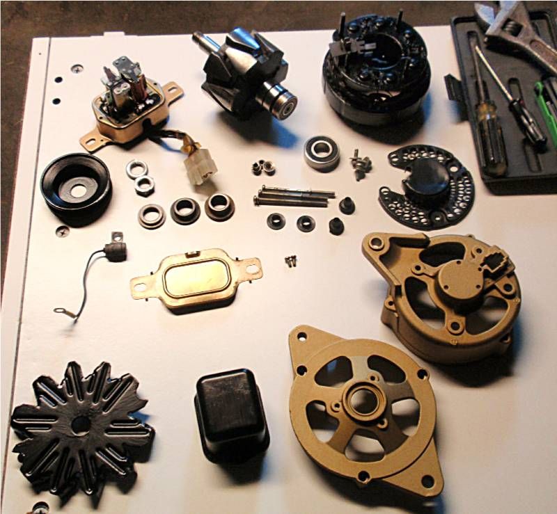
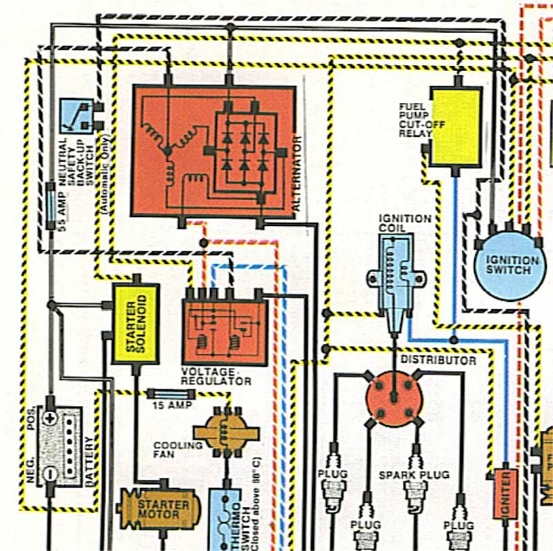
I have an old alternator off a 1981 Civic Wagon. The engine is kaput, but it still has lots of good parts. Like the alternator.
I made a note of each color wire was attached to the alternator before removing it, and also found a wiring diagram so I could identify the function of each connection:
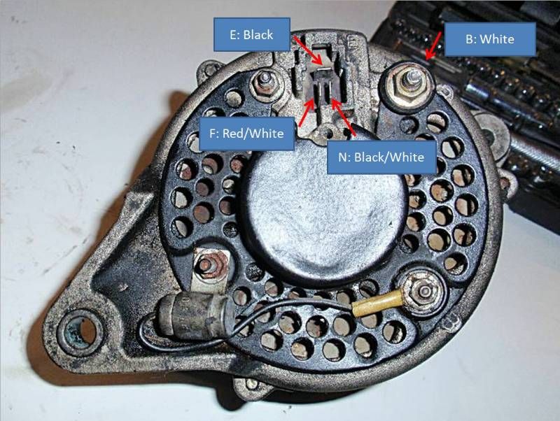
F: field coil +
E: field coil -
B: power coil +
N: power coil -
For anyone who doesn't know, (I sure didn't) alternators don't have permanent magnets in them. So in order to generate a magnetic field, power must be applied to the field coil. This means you have to put power into the alternator to get power out. This took a while to wrap my brain around.
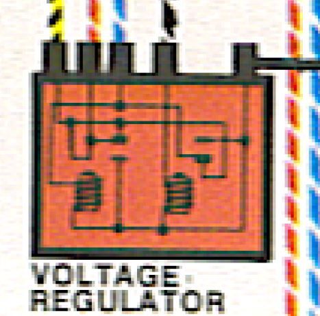
By the way, "field coil" and "power coil" may not be the proper terms for these components. I'm still learning this stuff. But at least they're descriptive, right? Also note, this alternator has no voltage regulator. Second Generation Civics have an external voltage regulator, which I won't be using.
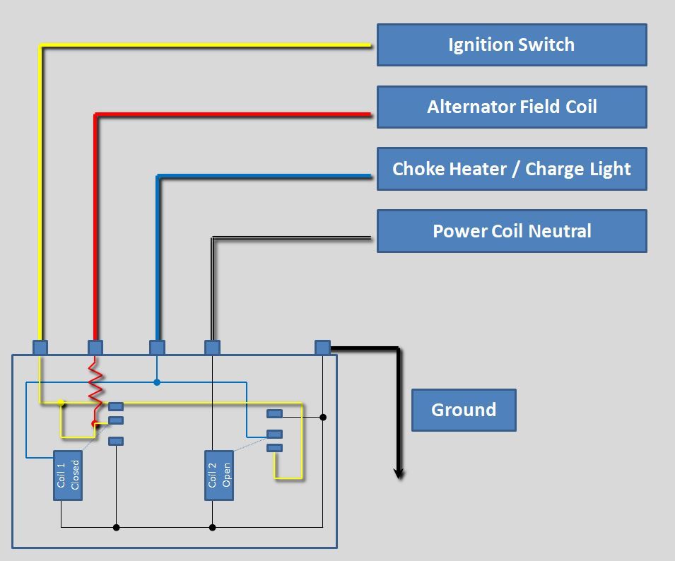
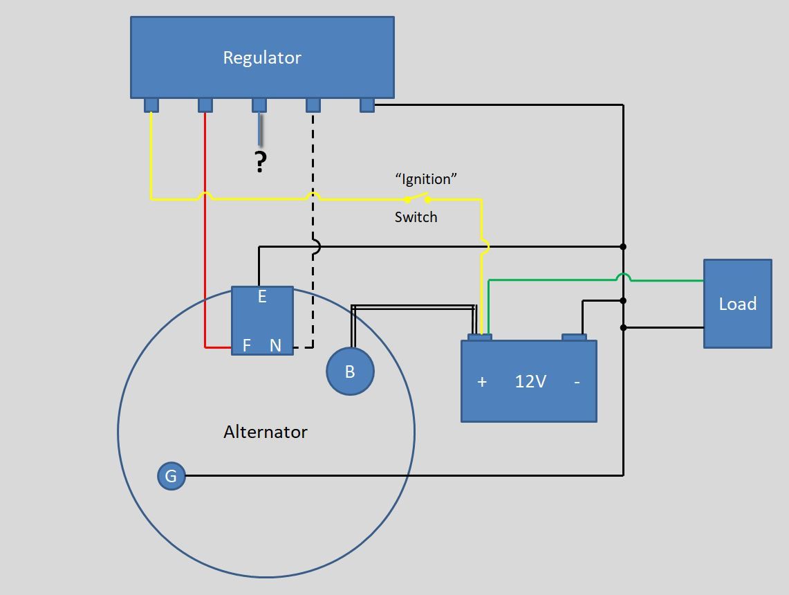
So a 12V battery on the field coil terminals will generate the magnetic field, and a multimeter or light bulb on the power coil terminals will tell me if its working. Also, its seems like a good idea to ground everything to the alternator casing, since that's how it's done in the car. Here's a diagram of how I plan to wire it:
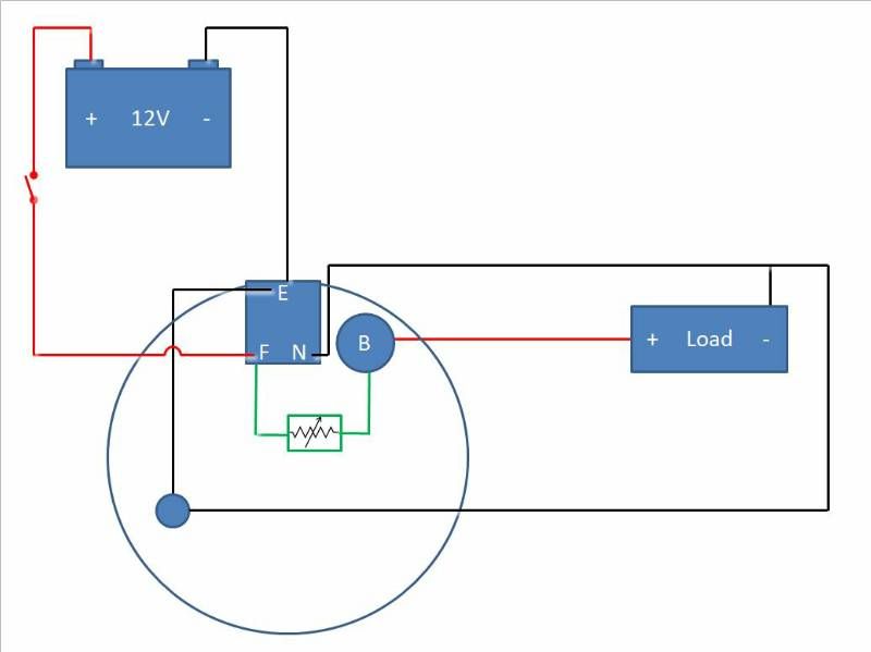
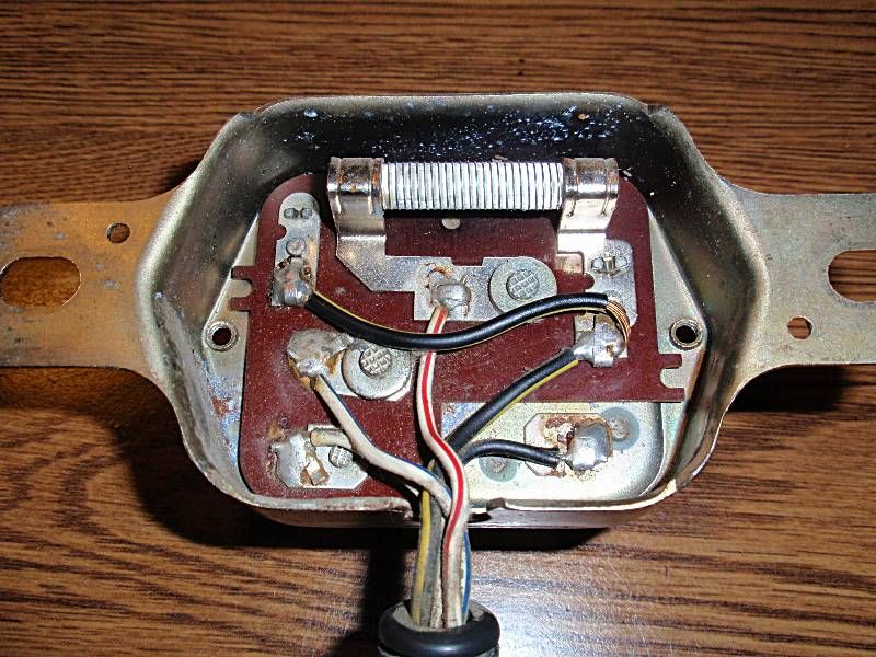
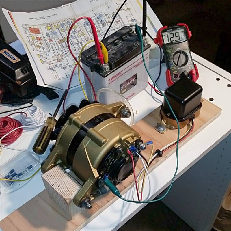
There's a couple features on this diagram that I haven't used yet. The switch to the battery, and the jumper from B (power coil +) to F (field coil +). Those I'll add later to try to make the field self-sustaining. For now I just want to see if I can make it work. Here's my actual wiring:
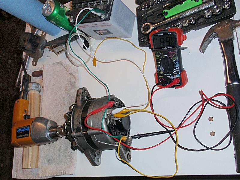
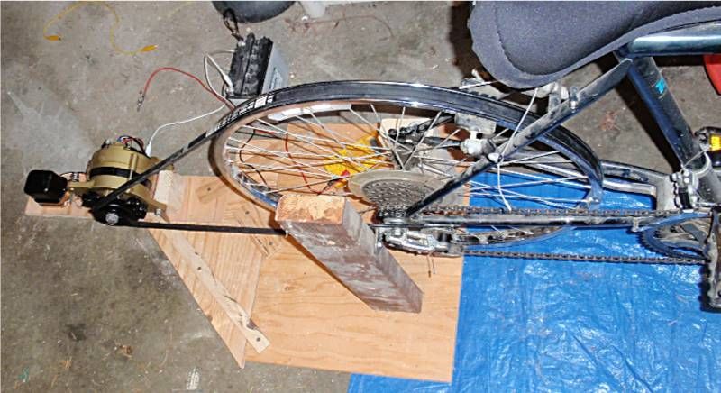
Well, the wiring is a mess, but I used a motorcycle battery for the field (which drew about 1.5A) and a hand drill to for rotation. It worked! The multimeter read around 15V, and when I hooked a light bulb up to it, nice and bright. Next is to clean it up better and put it on some kind of jig and replace the jumpers with proper wiring. Also, I need to find out at what RPM the alternator is meant to be used, and how many Amps can be safely drawn from it.
I made a note of each color wire was attached to the alternator before removing it, and also found a wiring diagram so I could identify the function of each connection:
F: field coil +
E: field coil -
B: power coil +
N: power coil -
For anyone who doesn't know, (I sure didn't) alternators don't have permanent magnets in them. So in order to generate a magnetic field, power must be applied to the field coil. This means you have to put power into the alternator to get power out. This took a while to wrap my brain around.
By the way, "field coil" and "power coil" may not be the proper terms for these components. I'm still learning this stuff. But at least they're descriptive, right? Also note, this alternator has no voltage regulator. Second Generation Civics have an external voltage regulator, which I won't be using.
So a 12V battery on the field coil terminals will generate the magnetic field, and a multimeter or light bulb on the power coil terminals will tell me if its working. Also, its seems like a good idea to ground everything to the alternator casing, since that's how it's done in the car. Here's a diagram of how I plan to wire it:
There's a couple features on this diagram that I haven't used yet. The switch to the battery, and the jumper from B (power coil +) to F (field coil +). Those I'll add later to try to make the field self-sustaining. For now I just want to see if I can make it work. Here's my actual wiring:
Well, the wiring is a mess, but I used a motorcycle battery for the field (which drew about 1.5A) and a hand drill to for rotation. It worked! The multimeter read around 15V, and when I hooked a light bulb up to it, nice and bright. Next is to clean it up better and put it on some kind of jig and replace the jumpers with proper wiring. Also, I need to find out at what RPM the alternator is meant to be used, and how many Amps can be safely drawn from it.

")