Why is my new hub motor making my controller super hot?

Doesnt' matter what wattage the motor is.

What matters is the load you put on the system, either thru your usage, or thru configuration, connection, or other problems.
 
I run more than 1200W through a 6 FET. Things aren't that simple.

Has the testing been repeated with the controller out in the airflow?

Has the testing with the 12 FET controller been done?

Has the no-load power and max speed for each motor been measured?

Here's a better simulator example, a pair of differently wound DD motors of similar to the type the OP is using, with fairly substantial changes in the windings.

The 2707 has more turns (7), and is referred to as a "slow" winding because it generates more back EMF and maxes out at a lower RPM on a fixed voltage. 35.4 kph will be the max speed of this one (level, no wind, default sim settings for bike, etc) according to the sim, and it will consume 450 watts. Battery current is 14.5A, motor current is 15.4A. Controller heating, is approximately 240 times R based on motor current. (*Note that this is also referred to as a "torque" winding, because given equal motor current this motor will produce more torque than the "speed" winding below).

The 2705 has fewer turns (5), and is referred to as a "fast" or "speed" winding because on the same voltage it will spin faster. 38.9 kph will be the maximum speed of this according to the sim, and it will draw 590 watts at this speed. Battery current is 20A, motor current is 24.7A. Controller heating is approximately 600 times R based on motor current, or about 2.5 times that of the other motor. Is that enough to create the "piping hot controller" you are seeing? R for a controller is a fairly small number (a few 10s of milliohms), so these heat levels are pretty low. Airflow would help.

Note that in each case you must look at the proper spot on the graph where the motor power crosses the load line. Looking elsewhere on the graph produces easily misunderstood results as the motor is accelerating or decelerating, only at equilibrium (load power = motor power) is the data applicable to continuous operation.
 

Attachments

  • windings01.PNG
    windings01.PNG
    563.2 KB · Views: 1,289
The last 2 posts are the only ones you need to read.
 
Voltron said:
Sure it's allowed... And low amps, like less than 5. Not 15 or 20.

And the new controller won't reduce your mileage... as long as you don't go punching it every block. But that is tougher than it sounds with a nice new more powerful controller :)

Alright! Ifinally got around to fixing new connectors on the load end of my watt meter.

My no load amp draw is 3-4 amps on full throttle. I did notice that it draws close to 20 amps in that first second or two before full throttle speed. But then it drops down to 3.somethiing amps.
 
Yes. It s with the 6 FET controller (or whatever my 600 watt controller is)

Still waiting for the new controller to arrive. My tracking says its being processed at an australia post in NSW (new south wales. )
 
Alan B said:
Good start.

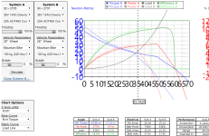
Unloaded max speed and battery current for both motors is what now?

Is this with the 6 FET controller? What is the status of the 12 FET controller?

Let's get all the data in one posting instead of dribbling it out.

How do I do an unloaded max speed test? The only way I know my loaded max speed is through an app on my phone that requires location services.

I'm not willing to test out my other motor right now because my phases are fused together and I don't have the bullet connectors to replace them yet.

I thought they were still separable but upon examination, they are well and truly seized. How do I separate them?
 
If there's no integrated speedometer on this bike then measuring wheel RPM and computing speed would work. Knowing motor speed and voltage we can compute Kv for each motor and try to match to the sim.

If we're going to do motor comparisons then working connectors are required.

What are the weights of the two motors? Are they both "9C" clones (similar diameter, width and weight)?
 
Alan B said:
If there's no integrated speedometer on this bike then measuring wheel RPM and computing speed would work. Knowing motor speed and voltage we can compute Kv for each motor and try to match to the sim.

How do I measure the RPM?

Alan B said:
What are the weights of the two motors? Are they both "9C" clones (similar diameter, width and weight)?

I don't have a scale but I can tell you that the new motor is 6.2 kgs, 24.5 cms in diameter and it supposedly has 520 max RPM. Torque of 2.5 N.M.

Bushing size: Diameter: 1.5 cm, height: 3.5 cm.

That's going off
the advertised description of course. I'll measure the other motor when I get home tonight. I know for sure that the new motor is heavier. I would say its at least 1.5 kgs by feel.

I think I can dig up a pic of the old hub.
 

Attachments

  • IMG_20170426_140621__1493198916_49.196.163.58.jpg
    IMG_20170426_140621__1493198916_49.196.163.58.jpg
    34.3 KB · Views: 1,249
Alan B said:
What voltage does the 520 RPM correspond to?
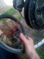
48 volts. If your talking about the battery pack. The motor voltage wasn't specified. Except of course, what system its compatible with. (I think,... I'll have to check)
 
If they don't specify a voltage for that RPM, then it's meaningless. A typical hubmotor only spins at a specific speed at a specific voltage.

At a higher voltage it spins faster, and at a lower voltage it spins slower.

Unless they tell you what voltage the 520RPM is at, then the RPM number provided is not useful. You'd have to test the RPM yourself, or calculate RPM based on the wheel speed and diameter (easy to google calculators for that phrase, or the formula to do it without one).
 
Alright! Finally received the new controller. That's the good news.

The bad news is that they messed up the connector specifications I requested. Aside from giving me the large bulky anderson instead of the power poles (that's fine, I'm moving on to bullets anyway) for the battery connector, they have me some complicated looking connectors for the throttle.

I have to try to wrap my head around this. There's the LCD and from reading the manual they emailed me, there's a way to leave that out but it involves only 2 wires. My throttle has 3.

I'm confused AF. My throttle has the positive red, the negative black anf the signal green.

Hers an image of what they sent me.
 
The photo is too bad to get anything meaningful from it. If thr throttle is a 5 wire one, it's normally because it has LEDs and a switch. Two wires are independent for the switch. One wire carries battery voltage to the LEDs and the remaining three are for the throttle. Maybe yours is different. You didn't show the throttle itself.
 
d8veh said:
The photo is too bad to get anything meaningful from it. If thr throttle is a 5 wire one, it's normally because it has LEDs and a switch. Two wires are independent for the switch. One wire carries battery voltage to the LEDs and the remaining three are for the throttle. Maybe yours is different. You didn't show the throttle itself.

Ah yeah, sorry about that. I should have zoomed in on the sucker. Turns out I was looking at rhe wrong connector. Thats for the LCD and electric lock.

The vendor clarified and emailed me the instruuctions. Its actually a JST connector thats kiinda grouped with the PAS and a speed controller sensor.
 
I can't change over the controller until I have the right connectors. I'm gonna have to replace the phases with new bullets but I can't use the cheap ones I got for the battery connectors. The insulations they came with is already melting through and I was only able to solder the male ends because the female's insulation (which I had to put on the wire first) wasn't allowing me to get any solder in. I ordered some banana bullets.

And to make this transition more challenging, I can't get the halls separated. The plastic housing still has movement but try as I might, can't get them apart. I wonder if the pins have fused for the halls too.

I really don't want to have to redo the halls. That's a fiddly job that I'm no good at. In fact, every connector I have to do myself, I always end up having issues with down the track.
 
The pins are held in with a barb. You need the smallest jewellers-type screwdriver to hold down the barb while you pull the pin out.
 
No, what I meant was that the make and female ends off the halls are still locked together. I can't even get to the part where I have to press the barb.
 
Hey guys, I need your help.

I finally got my hand on some decent bullet connectors. I'm in the process of instaling the new controller and after doing all the hall connectors, the phases and the throttle, when I twist the throttle, I get like 1 mm of wheel movement followed by a click sound and then nothing.

What is that? Is it a hall sensor issue? I need to be back on the road ASAP. please help.
 
Did you do the testing to find the correct phase/hall wiring combination for your new controller vs the existing motor?

If not, you have to do that first. There is an article in the Wiki and numerous threads on the forum about how to find the right hall / phase wiring combination (combo), if you have not done this before.

If the controller has a learn function you can try that first, otherwise you must manually find the right combination.
 
ClintBX said:
Hey guys, I need your help.

I finally got my hand on some decent bullet connectors. I'm in the process of instaling the new controller and after doing all the hall connectors, the phases and the throttle, when I twist the throttle, I get like 1 mm of wheel movement followed by a click sound and then nothing.

What is that? Is it a hall sensor issue? I need to be back on the road ASAP. please help.
When you mix and match controllers with motors, the connection sequence is often not colour to colour, so you have to find the correct sequence by experimentation. There's 36 combinations of which three should work correctly.
 
amberwolf said:
Did you do the testing to find the correct phase/hall wiring combination for your new controller vs the existing motor?

If not, you have to do that first. There is an article in the Wiki and numerous threads on the forum about how to find the right hall / phase wiring combination (combo), if you have not done this before.

If the controller has a learn function you can try that first, otherwise you must manually find the right combination.

Yeah, I tried different phase combinations. I didn't do the halls though because swapping the pins in and out is a bitch at 5 in the morning after a long and frustrating night.

I've read a few of those threads but I thought that false combination results in either a rough wheel movement, backwards or smooth. Can it also result in what I'm experiencing? The last time I had a similar symptom was when I tried paring my first 48V battery a 36V controller.

....should I start with the blue and green on the halls?


The good news is that because I HAD to do all the connectors over on my current controller, I'm able to test different phase combinations. So far, I discovered that all the 2 color swaps results in reverse. I'm trying a total mismatch of the BYG and it runs just as smooth as before. I'll monitor that controller heat to see if she still cooks.
 
Back
Top