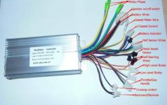
Why is my new hub motor making my controller super hot?

I'm asking my vendor some questions and all he can tell me its that I need a display for this controller to work. I hope that's not so. I like my current throttle and I want to Change it.

Is there such a thing as display system only controller or is my vendor a bone head trying to sell me more stuff. (Sorta how I bought the controller from him)

It even says right in the manual, if I don't have an LCD throttle to plug it into a....

I'll upload the manual soon to see what you guys can tell me.
 
ClintBX said:
I'm asking my vendor some questions and all he can tell me its that I need a display for this controller to work. I hope that's not so. I like my current throttle and I want to Change it.

Is there such a thing as display system only controller or is my vendor a bone head trying to sell me more stuff. (Sorta how I bought the controller from him)

It even says right in the manual, if I don't have an LCD throttle to plug it into a....

I'll upload the manual soon to see what you guys can tell me.
If the controller has a designation on it that begins with KT, the chances are that you need the LCD to do all the settings; however, that won't solve your problem. You need to go through all combinations to see what works.
 
Alright, a quick update on my current controller's configuration.

Since redoing all the connectors, I'm finally able to check on all 6 combinations of the phases.

That was the first thing I did before leaving the house.

First I tried the 3 two color swaps.
Y->Y, B<->G
G->G, B<->Y
B->B, G<->Y

All of which resulted in the reverse gear.

Then I tried the total colour mismatches (TCM).

I gotta say, there's no difference in performance or sypmtom with either of the 2 total mismatch as there is with the perfect match combination.

The no load, full throttle amp reads at around 2-3 amps continuously.

The only thing I noticed from that last combination mismatch (I only just tried it today and rode 15 km before changing it to the other TCM) is that it felt a little grainy to ride .Still smooth but (and I may be halucinating this) with a little more friction than usual. And when I touched the controller, it seemed even hotter to the touch (again, I may be imagining it)

The first total mismatch I tried yesterday is what I have set on right now. I haven't ridden on it yet to determine if the "grainy" feeling is there anyway or if the other combination was indeed a less optimal one.

I've also checked on my voltage to see if any of the functional combinations were draining more. By around 10 kms to the city (my usual commute), I still have a healthy 52 volts left.
 
Now, onto the topic of the new controller. I'm uploading the instruction manual to see if there's anything I missed.

I've tested it on both my newer motor and my previous motor and I've tried 2 different throttles. And the results are the same. The wheel twitches, followed by a small click sound and then nothing.

I've tried a few phase wire combinations (though I wasn't thorough) and nothing changed.
I've also tried taking out some of the closed circuit loops to see if that was effecting it, (the cruise control, the electrical brake and the LCD). When I removed any of them, there wasn't even the twitch thing I'm getting. I think the motor gets no power at all. (They're there for a reasonI guess)

I guess all that's left is to do a thorough phase and hall combination diagnostic (why does this have to be so freakin' hard!)

Unless you guys have any other suggestions.
 

Attachments

  • Controller Connection Manual.pdf
    351 KB · Views: 56
I'll say it one more time. There's 36 combinations of hall and phase wire connections. Three combinations will give correct forward rotation and three will give correct reverse. You need to try all 36 combinations to find the three that give the correct forward motion. Due to small differences/tolerances, one combination often works slightly better than the other two.
 
When the wheel twitches and the system clicks, the controller has determined that the hall/phase combo is wrong and is going into a self protection mode. Otherwise it could be damaged. Very large currents are likely flowing at that time combined with a lack of expected motion, triggering self protection.

A grainy feeling in the throttle is almost certainly a wrong phase/hall combo, don't use it.

Don't give much throttle at all unless everything is smooth and power remains low. Damage could result, such as popping a FET. Don't run any wrong combination. Find the right combination and don't keep experimenting as this puts the controller at risk. Keep the throttle level low during this testing until the proper combo is found. Only when it is running very smoothly at low throttle should it be run to higher speeds. The goal during testing is to stop at low throttle on all wrong combinations.

Be very careful, and get the setup working smoothly from zero to full throttle and with low power at full RPM unloaded before trying any road testing. Don't road test any lesser combinations.

Modern controllers often have an automatic search mode to find the right setup without moving any wires. This may require the display. This is very convenient, but swapping the wires to the right combination should also work. The display may also provide other diagnostics or controls to set the controller up. Some controllers don't work without the proper display as they are communicating with it.

Of the 36 possible combinations, the 3 that produce proper operation are rotations of each other. They are equivalent. If they are not the motor or controller are flawed, and this cannot be fixed by swapping hall/phase wires. The controller and motor both rotate through the firing of the FETS and the poles of the motor all the time, if they are not symmetrical then the system will never work optimally.

Good solid connections with no possibility of shorts is important. Don't take any chances. Remove power and allow voltage to dissipate prior to moving any connections. One momentary short or voltage spike can damage things in strange ways and ruin the day.

A controller can be damaged or flawed in ways that make it "mostly" work, as can a motor. For example, shorted turns in a motor may allow the motor to work, but very inefficiently.
 
Alright, another update on the situations.

Regarding the new controller: After testing it again (mainly to shoot a video to send to my vendor) it started working .... but only momentarily as I discovered that it responded differently based on where or how the wires were hanging.

So, I'm less certain that it is a hall sensor combination issue. I also tried out the 6 phase wire combinations and saw no difference or change in any of the 6 combinations.

The question is;
Is there a bad wire or is it still indeed a bad combination in the halls? Or maybe a bad connection in the controller? How do I know?

Here's the link to the youtube video if you care to take a look and maybe help me out.

https://youtu.be/31qAlIqlncM

[youtube]https://youtu.be/31qAlIqlncM[/youtube]

Regarding the current controller: With the phases, I'm set on my second last combination which is a complete color mismatch of(from controller to motor) Y->G, G->B and B->Y. Only because I found this to be the smoothest riding experience of the 3 forward spinning combinations. It's so subtle though that I'm not sure its real. All I know is that the controller runs hot amongst all the combinations and still at a healthy 2-3 amps unloaded full throt.

I still get some heat running through the phases. In fact, (and I find this funny) to the point that some heat shrink that I hadn't gotten around to shrinking yet shrank itself from the heat. But just around the green controller phase. The other 2 are still loose.

The question now is;

Should I look for hall sensor combinations to see if I can find a cooler running combination? I'm hesitant to f#ck around with more combinations and having to test ride it just to see if it gets hot on potentially damaging combinations.
 
I sort of feel sorry for you, and I want to help, but if you don't do what we suggest, how can we help?
Release all the male pins from the connector, then you can plug them into the the other side in any sequence you want.

Another thing: That looks like a KT controller. They have a parameter that you have to set to match the motor. It's P1 = number of magnets÷ reduction ratio. Your reduction ratio is 1. You need the LCD to set this parameter.
 
d8veh said:
I sort of feel sorry for you, and I want to help, but if you don't do what we suggest, how can we help?

If you were actually reading this thread instead of skimming, you'd know I've been trying my best with the equipment I've got.

I ignored your last comment because you totally missed that I was on the same page about the hall sensors and I wanted to focus on some of the more constructive and respecful feedbacks.

I'm not super experienced with this stuff and unlike some people, I don't have a lot of time on my hands to play around with this stuff. You know, I lost several nights sleep because of the shite I had to fix around all this, let alone just trying to figure it out.

So excuse me if I'm a little slow to go and mess with hall sensors which are a pain to pin an unpin, super time consuming and frustrating as f#ck when I have to redo a pin or the whole damn connector because I messed it up the last time.

Moderator removed inappropriate text.
 
d8veh said:
Another thing: That looks like a KT controller. They have a parameter that you have to set to match the motor. It's P1 = number of magnets÷ reduction ratio. Your reduction ratio is 1. You need the LCD to set this parameter.

Ok, now to you're speaking greek.

Yes, its a KT controller (aren't they all?) But it has a no LCD mode. Why would that be there if therss something that has yo configured only with an LCD? And is that the issue or are you just throwing that in there? (I hate it when people point out a problem thats not even related to the issue experienced. )
 
This thread is going off track. It will be temporarily locked for a cooling off period. Do not start another thread on this topic. Some inflammatory text has been edited by a moderator. It will be unlocked in a few days.

The original poster is encouraged to reread this entire thread and consider that the suggestions already given cover the subject material thoroughly. The hall sensor and motor phase connections must be made correct regardless of whether or not it is easy to do so. Phase and hall signal wire colors are not always matched when things are correct. A display is needed with some controllers. Not all questions can be answered from insufficient information, and there are many products on the market these days.

Thanks to all who are attempting to help.
 
Here is an excerpt from my Bonanza ebike thread, where I had the same problem to solve:

BLDC Hall Sensor and Motor Wiring Combinations

I had to search the motor timing on this build. Interesting process. The Lyen motor tester showed me that everything was working but didn't directly show which phase combination was the one. It did help though.

On my new setup it is not easy to change the wiring of the hall sensors (small pins in a connector), so I wanted to minimize that. There are six combinations of hall wiring, but due to rotation symmetry only two combinations are truly different. One is forward hall rotation, one is reverse. You can see this with Lyen's tester. Fechter also diagrammed a simple hall tester with three LEDs and three resistors here on ES.

For each hall wiring combination there are six combinations of motor phase. These are currently individual powerpole connnectors on the motor wires so they are easy to change. Thus minimizing hall wiring changes is the best technique for this bike.

So the process becomes:

Test each of the six combinations of motor phase wiring (for one hall wiring combination). One of those will be the correct motor connection for this hall connection and produce smooth motion up to full speed and have the lowest power consumption over the whole throttle range. This motion could be in the forward or the reverse direction. If it is forward motion, you are done. No need to try any more combinations.

If the motor is running properly but in the wrong direction, swap any two of the hall sensor wires (leaving ground and power alone - never change them) and try the six combinations of motor phase again. One of these will be the correct one. Six or Twelve total arrangements to test. Not thirty-six. The other 24 are simply rotations of the first 12. No need to explore them.

Test with very gentle throttle (wrong combinations at high throttle can cause damage). It should rotate smoothly forward at very low current. If that works gently ramp up the speed, the current and speed should rise smoothly some but the current should remain low (unloaded wheel spinning). STOP if the motor is not smooth or takes more than a small fraction of your full current (perhaps 5%). If the motor is a gearmotor it won't rotate the wheel when the motor is running in reverse, but you should hear the motor running inside.

On the motor phase wiring, make sure to explore all six combinations. Assuming three colors:

1) colors matching through (one combination)
2) one color matched, other two not matched, for each of the three colors (three combinations)
3) no colors matched (two combinations)

Make sure to try all six of them, it is easy to miss one, and that can be the right answer.
 
Hey guy,

Just another update. While still in the process of figuring out the new controller, I discovered something interesting. I noticed that when I move the wheel by hand so it spins and then I turn the throttle, the wheel locks immediately.

Once I can get a useful tool and some free time, I'm gonna free my motor's halll sensor pins to test some combinations.

I'd also like to make the process a 2fer and figure out if there's another hall sensor combination that doesn't burn my current controller up. I'm still replacing phase connectors like they're underwear. I have no idea how I'll be able to discern this better hall combination though. I think there's a method using a multimeter but I have no idea what settings and my leads are broken. (I'll be hunting some new leads tomorrow)
 
Not surprising. The halls tell the controller where the wheel is, and it provides current to the phases. When the timing is wrong, the current won't necessarily aid the motion, instead it may oppose it, which would stop the motion.

Choose the combination that produces smooth motion with minimum current. That's all you can do.

If things are still getting hot, there may be a short in the motor or wiring, or some other problem.

With a meter you could test to see that all the hall sensors are working.
 
Ok, ive tried out every hall combination on my current controller. (Not counting the red and black). I see no difference between any of them. They all run smoothly. Maybe one of the total color mismatches jolts at first but they all run smooth.

I don't really know what to look for. If its a hall sensor combination causing the extra heat, how will I know?

I'm gonna flip the blue and yellow and road test it today to see if that has any impact but I'm afraid of doing damage. I'm not sure that I should do it.

I also tested every hall and sensor combination on the new controller but no luck whatsoever. Just the same motor twitch followed by a click and then nada.
 
So you are saying the hall sensor wiring doesn't matter with the old controller. Does it also work if the halls are disconnected? Sounds like a sensorless controller. If so, swapping two motor leads would make it run backwards. For a sensorless controller some twitching at startup is normal. Sensorless controllers don't use the hall sensors at all.

So the new controller doesn't work regardless of the hall sensor wiring, and always does the same thing. This sounds like the hall sensors are not actually working. Or the hall sensor wiring is bad. Did you measure the 5V (red/black) leads to the hall sensors with your new test leads? If the 5V is ok then measure each hall sensor voltage, it should alternate between 0 and a few volts as the wheel is rotated by hand (a digital signal).

I would not do any test rides with the overheating controller, or any setup that is not working properly. One exception might be testing the old controller with full airflow to see if that solves the overheating. But if adequate connectors are melting then something is drawing way too much current. If the wiring has been hot there might be melted insulation and intermittent shorts somewhere.

I think you said that you are melting connectors. Is that right? What connectors exactly are melting? When do they melt? Even if the controller is too small the connectors should not melt, unless they are also inadequate. This may point to problems in the motor.

If we assume for a moment that there is only one bad component, and we look at what one component could cause all the results you are reporting, the new motor is probably the only single item that could. Of course there could be multiple bad components as well. It only takes a momentary short or wrong connection to damage electronics. It is not very forgiving to some faults.
 
There's three types of controller. Plain ordinary ones, where you have to figure out the correct connection sequence; self-learning ones, where you need to apply a self-learning procedure to set the phase/hall sequence; and ones with automatic hase/hall angle and sequence detection. The last type don't care which connection sequence you use. They'll figure out how to work the motor regardless of connection sequence. They can be a real problem when they spin the motor backwards because they compensate for any changes you make to reverse the direction, though some have a reverse switch.
 
Alan B said:
So you are saying the hall sensor wiring doesn't matter with the old controller. Does it also work if the halls are disconnected? Sounds like a sensorless controller. If so, swapping two motor leads would make it run backwards. For a sensorless controller some twitching at startup is normal. Sensorless controllers don't use the hall sensors at all.

Thank you for bringing this to my attention. When I came home, first thing I tested was whether the motor still works with hall sensor disconnected. And guess what, she works sensorless.

This is strange because when I had this controller hooked up to my old motor, I had a few issues regarding hall sensor connections. I remember, for a while I had to keep the yellow hall senor in place with tape. I would also get a weird squeak if I throttled to hard on take off. It had this really jarring delay. I had to be extra delicate on take. Like more than natural.

Here's something else I don't get. My 600 watt controller doesn't have a sensorless function. Unless its something I missed. I'll include an image of all the features i have.

It could be that the sensor feature crapped out entirely. About a week and a half ago, the motor did this weird jarring stalling. When I looked at it, I saw the black hall sensor wire had somehow gotten some exposed wires. (I suspect it had been melted by contacting either the side of the controller or the phases). I assumed that the halls shorted because it either made contact with one of the phases or one of the other halls (The green and the blue had smaller bit of exposed wire)

I've since replaced the connector after chopping the hall wires below the damaged section. I also make sure that all the wires are coming out the top and exposed to the air while spaced out from one another as possible.
 

Attachments

  • My controller's specs__1497122209_27.33.228.220.jpg
    My controller's specs__1497122209_27.33.228.220.jpg
    14.4 KB · Views: 1,098
I see some self-learning wires there. That process usually takes a while and rotates the motor slowly. That requires working hall sensors.

Sensorless controllers usually start a little slower, or require the wheel to be turning before they start.

Since you had shorts then things may well be damaged. The halls cannot take the voltages fed to the phases, even for a very short time. The controller hall inputs may be damaged as well. So you may have both damaged motor hall sensors and a damaged controller, maybe even both controllers are partially damaged in the hall sensor input side. They are designed for low voltage signals, the motor phase power is full battery voltage (36/48V?). They don't mix well.

The wiring and connectors need to be solid. Even a momentary problem can damage things. Don't ever let the hall signals and the motor signals intermingle. Problems in the cabling can ruin both motor and controller.

If the hall sensors in the motor are bad you'll have to disassemble the motor and replace them, or just run it sensorless. Which requires a sensorless capable controller.

If the sensor inputs on a sensored controller are bad it will need to be replaced. That's not a user repairable problem.

The simplest thing to do is get a motor and controller from same source as a pre-tested matched pair with matching connectors already installed.
 
I see. I'm still curious how it is that my controller its now working sensorless. I'm going to test it on my old motor to see if SHE works without the halls plugged in.
 
Some controllers that come wired up with hall sensor wires don't bother to use them at all, even when connected to working hall sensors, even with a self-learn function.

I have two of those, on my SB Cruiser trike, by different makers but based on the same CPU.
Thread for one of them:
https://endless-sphere.com/forums/viewtopic.php?f=2&t=68501
It has all green phase wires, and all green hall sensor wires.
On the other one it has colored hall wires and phase wires(yellow, green, blue).
 
Another thing that was brought to my attention after watching a youtube video of someone that was getting similar issues with heating pointed out the different gauge wires for the phases.

I told him about the experience I'm having and mentioned I too have thinner wires for the motor than the ones on the controller.

He recommends to change the phase connectors to AWG 14 1/4 or better still 12 gold plated. He reckons its an amperage resistor issue.
 
ClintBX said:
I see. I'm still curious how it is that my controller its now working sensorless. I'm going to test it on my old motor to see if SHE works without the halls plugged in.

I tested my old motor with the hall disconnected. It too worked sensorless. It's a controller quirk.
 
Back
Top