TSDZ2 mid drive with 860C, 850C or SW102 displays only -- Flexible OpenSource firmware (Casainho code only)

casainho

10 GW
Joined
Feb 14, 2011
Messages
6,047
Project status as of 2020.01.17: full working and tested, other developers did join and users are very happy, including online shops selling the TSDZ2 motor and 850C displays with our firmware installed.

About the TSDZ2 Flexible OpenSource firmware/embedded software

This OpenSource firmware adds advanced features and customization that are usually only available on expensive motors from big brands. The motor is driven more efficiently (FOC) making it stronger and uses less battery energy. It also allows the use more advanced displays like the 850C color display and SW102 Bluetooth display.

The displays show advanced information like battery voltage, rider pedal power in watts, motor temperature, etc. All configuration is available to the user via the display!

The development of this firmware started on March 2018 by casainho and 6 months after, Jabalat an experienced user of TSDZ2 and ebikes, did a very positive review on his Youtube channel. The development is active and is being done for free by the community of users; some of these developers work professionally developing this type of technology for very well known companies.

Project page: https://github.com/OpenSource-EBike-firmware/TSDZ2_wiki/wiki

---

With the same spirit of Flexible OpenSource firmware for BMSBattery S/Kunteng KT motor controllers (0.25kW up to 5kW), that I started 1 year ago (on 25 April 2017), I just started the research for development of OpenSource firmware for TSDZ2 motor controller -- my notes are here:

https://opensourceebikefirmware.bitbucket.io/development_tsdz2/About_Tongsheng_TSDZ2_mid_drive_motors.html
 
you can find details on the torquesensor here:
https://www.pedelecforum.de/forum/index.php?threads/funktionsprinzip-drehmomentsensor-im-mittelmotor-sfm-du-250-p-tsdz2.45029/
I wonder, how the working frequency for the sensor will be generated and the signal processing will be done in the firmware :?

regards
stancecoke
 
stancecoke said:
you can find details on the torquesensor here:
https://www.pedelecforum.de/forum/index.php?threads/funktionsprinzip-drehmomentsensor-im-mittelmotor-sfm-du-250-p-tsdz2.45029/
I wonder, how the working frequency for the sensor will be generated and the signal processing will be done in the firmware :?
THANKS!! you did a great works as always!!
 
VICTORY!!

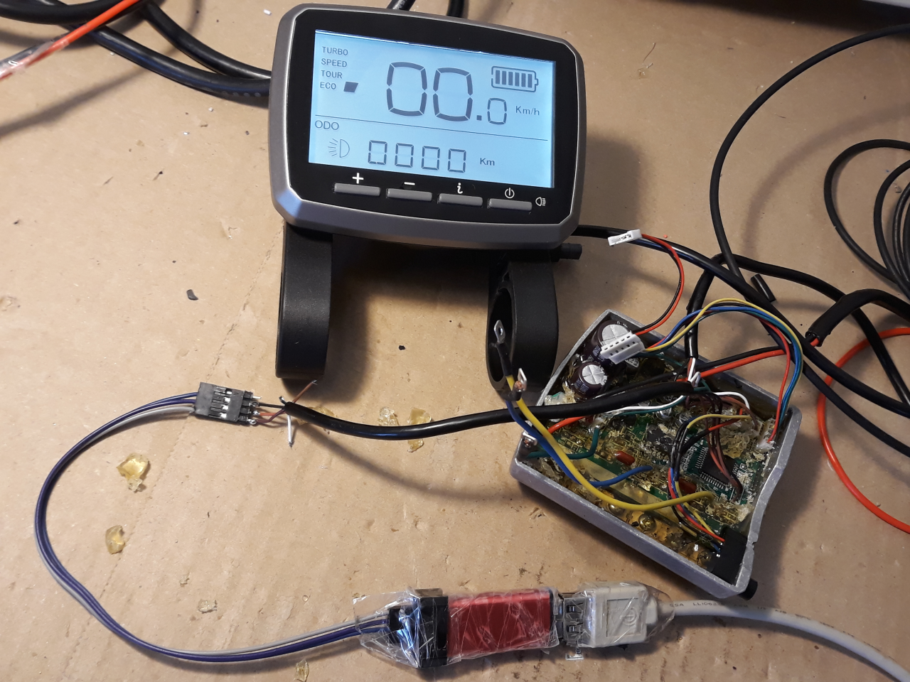
The connection for firmware programming and debug are available on the connector for the speed sensor.

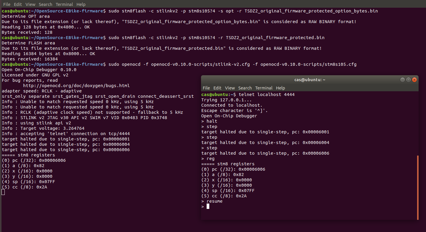
Seems that the original firmware is not read protected. I was able to read the option bytes, firmware and finally connect with OpenOCD for a debug session.

Please read my full notes here: https://opensourceebikefirmware.bitbucket.io/development_tsdz2/Various--2018.04.18_-_original_firmware_and_debug_session_using_OpenOCD.html

3-2.png


3-4.png
 
well done, a quick prevision of the possible customization? (I'm interested about current limit)
 
e3s said:
well done, a quick prevision of the possible customization? (I'm interested about current limit)
I guess that alone, I will not take less than 10 months. If other developers and brave testers like Stancecoke join, maybe in 3 months.
 
Hi Casainho, watching with interest!

FWIW: Looks like someone else is offering updated firmware: https://www.youtube.com/watch?v=tj2aYtma64o

Obviously a "how to load the firmware" instruction video for people who have bought his disc. Not very informative, but may be of interest.

I couldn't spot any mention of software relating to the TSDZ2 controller on their website ( http://btn-ebike.com/index.asp ) , but in the "news" section it does imply they supply software for tuning the BBS units: http://btn-ebike.com/newsshow.asp?showidd=497&classid=003 and the company lists videos about that subject, but nothing on the TSDZ2 software.

Best of luck with the project,
Dave
 
Thats an old video that just tells how to upload a certain controller profile that they were sending to someone... its like I have files for 48v18a, 36v13a, 52v17a, etc etc, and once I connect the motor to the computer/program, I can choose to save whichever one. Also, if you know what is what, you can modify other settings, or just the current etc with this... This is the method I use for programming controllers right now, and it is extremely limited/difficult to modify specific settings as opposed to just uploading a motor/controller profile like the video shows.

I think what casianho is doing will be much better, with several parameters customizeable, and more user friendly!
 
Drum said:
FWIW: Looks like someone else is offering updated firmware: https://www.youtube.com/watch?v=tj2aYtma64o
Thanks!!
 
eyebyesickle said:
Thats an old video that just tells how to upload a certain controller profile that they were sending to someone... its like I have files for 48v18a, 36v13a, 52v17a, etc etc, and once I connect the motor to the computer/program, I can choose to save whichever one. Also, if you know what is what, you can modify other settings, or just the current etc with this... This is the method I use for programming controllers right now, and it is extremely limited/difficult to modify specific settings as opposed to just uploading a motor/controller profile like the video shows.

I think what casianho is doing will be much better, with several parameters customizeable, and more user friendly!
I would like to validate the information I learned on this process.
1. Can you please confirm that you have some cable (STLinkV2??) that is connected to the cable that goes to speed sensor?
2. And the software for reading and writing, is something specific or the Windows version of ST for flashing this microcontrollers?
3. Are you reading and changing the EEPROM area of the microcontroller and/or the flash area?

It is not just firmware, It is also all tecnhical details about the system, even like the LCD :)
 
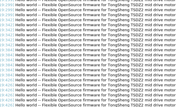
First code runs, the traditional “Hello world” using printf() :)
The sources for the firmware, were I put this very first code, are available here: https://github.com/OpenSource-EBike-firmware/TongSheng_TSDZ2_motor_controller_firmware

5-1.png


5-2.png


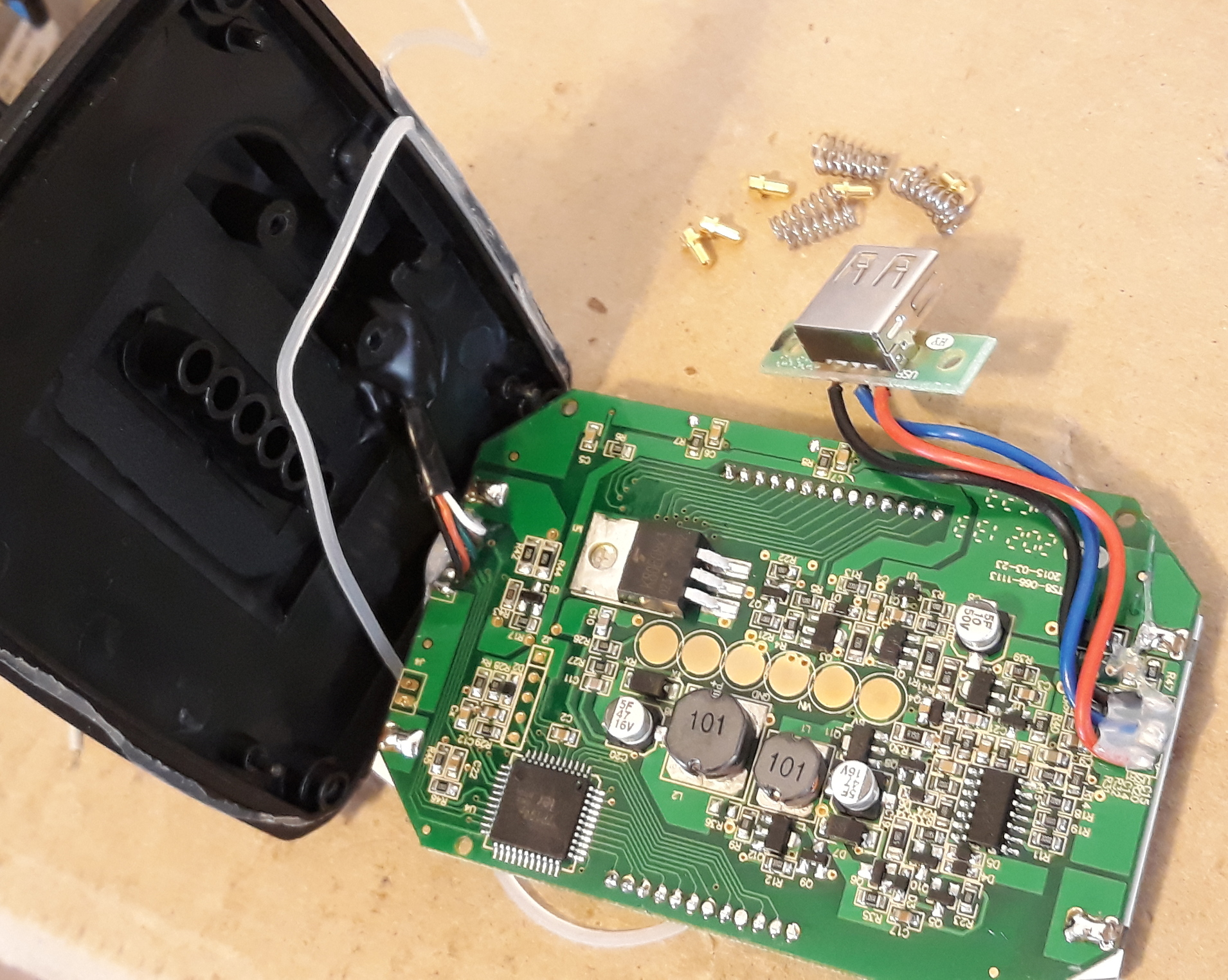
And I got more info about the VLCD5 -- see all my notes here: https://opensourceebikefirmware.bitbucket.io/development_tsdz2/About_Tongsheng_TSDZ2_mid_drive_motors--LCD_-_VLCD5.html

NOTE: the motor controller can be enabled by simple connect green wire to white wire and this way there is no need to use LCD.

4-2.png


Cable from motor controller | PAD on LCD PCB | notes
• green | P+ | battery voltage!!
• black | GND | ground
• white | Vin | ground when LCD disabled and P+ (battery voltage) when LCD is enabled
• brown | RX | UART TX motor controller
• orange | TX | UART RX motor controller
• purple | not connected | this cable is not connected to any PAD
• not available | 5V | the PAD has 5V label but seems it is not connected
 
This is the totally fun part of the project, you must be having a ball!!!
 
Some experience with openocd here. I also have a tsdz2 (though a noisy one). If you need some help, let me know. Also I have the buggy XH 18 display, and would be interested into fixing it.
 
qwerkus said:
Some experience with openocd here. I also have a tsdz2 (though a noisy one). If you need some help, let me know. Also I have the buggy XH 18 display, and would be interested into fixing it.
Thanks. OpenOCD and debug works great on Eclipse.

All the help is welcome. If you want to get involved, please look at the code in github and maybe you can participate in some part...
About displays, the ones used by Kunteng are cheaper and the code is already done, and they communicate through UART as XLCD5, so is just a matter of wiring.
 
I just tested and found that the firmware I did read from the motor controler is ok and I flashed it back and it works :)
I also did a backup of opion bytes and EEPROM.
This means we can test the firmware and go back to original one when we want.

I would like to disassembly the firmware binary file as it can give some clues... Does anyone knows how to disassembly STM8 firmware bin files?? The file is on the project page.
 
casainho said:
Thanks. OpenOCD and debug works great on Eclipse.

All the help is welcome. If you want to get involved, please look at the code in github and maybe you can participate in some part...
About displays, the ones used by Kunteng are cheaper and the code is already done, and they communicate through UART as XLCD5, so is just a matter of wiring.

Never worked with eclipse, but why not. What I did was hardcore rpi openocd fixing of bricked routers - nothing really fancy. Thanks pointing out the code done on Kunteng, but there is no way I would give up the XH 18 grip shifting. As a matter of fact, other expressed interest into it (for an instance coupled with a bbs) so there is a lot of potential. I think we could make the XH 18 an "universal" display + shifter. Will have a look at your code once I dig out the rpi...
 
casainho said:
eyebyesickle said:
Thats an old video that just tells how to upload a certain controller profile that they were sending to someone... its like I have files for 48v18a, 36v13a, 52v17a, etc etc, and once I connect the motor to the computer/program, I can choose to save whichever one. Also, if you know what is what, you can modify other settings, or just the current etc with this... This is the method I use for programming controllers right now, and it is extremely limited/difficult to modify specific settings as opposed to just uploading a motor/controller profile like the video shows.

I think what casianho is doing will be much better, with several parameters customizeable, and more user friendly!
I would like to validate the information I learned on this process.
1. Can you please confirm that you have some cable (STLinkV2??) that is connected to the cable that goes to speed sensor?
2. And the software for reading and writing, is something specific or the Windows version of ST for flashing this microcontrollers?
3. Are you reading and changing the EEPROM area of the microcontroller and/or the flash area?

It is not just firmware, It is also all tecnhical details about the system, even like the LCD :)

1.) Yes, I took the connectors that came with the STlinkV2, and wired them to a TSDZ2 speed sensor extension cable that was cut in half.
2) Windows ST Visual Programmer ~ STlinkV2 software
3) Data Memory is the area for manual adjustments of voltage and current, you can change a couple values and edit manually. Otherwise, I just load the whole program memory AND data memory for easy programming, from pre prepared files I have.

On a side note, I may try to get these running with NO display. I think to have a model (coaster brake version, im thinking) where there is NO display, and NO speed sensor, that would be super slick and clean. JUST the pedal assist, as long as we can make it automatically come on when the battery is powered on, I would just leave it at 3/4 assist =).
 
I think this sensor that is screwed on the motor controller but is in visual line with the crank, is a PAS sensor. I verified it has signal 2 wires output (digital signal) that reacts when I pass a magnet in front of them and seems is a kind of quadrature signal and this way should be possible to detect if pedals are rotating forwards or backwards.

Question: I didn't saw any magnets on my crank, can you guys say if the crank has magnets??


Speady said:
There's only tiny magnets next to the hall sensor that enables torque sensing.
Thanks.

Speady said:
Wouldn't spend much time in searching for a PAS.
Why do you say that?
 
I don't know what you have in mind with a PAS Sensor.
There's quite a few software bugs you can patch instead.
The display cuts off after rolling a couple minutes without assist, the LVC and OVC need to be made adjustable to make the unit work on a 11S battery, and a soft start ramp would be nice too. So let us improve the programming in the first place.
 
As far as I remember, the PAS magnets are in the outer ring of the secondary coil.

Regards
stancecoke
 
Back
Top