EasyDIY OpenSource display for EVs: TSDZ2 and Bafang M500/M600 EBike motors

kaziq said:
casainho said:
And isn't that the 0.96 inches display?
Nope. Definitely 1.3 inch.

casainho said:
Anyway I would suggest you to flash all the 4 versions, just to see how things happen.
Both 1.3 and 0.96 SPI produce the same output. With I2C versions the display stays black, and the nRF board does not seem to start (led stays red).
Okok.

I wounder if the firmware was correctly built, as I remember, the 1.3 version works on 0.96 version but I would see a similar result. If not, well maybe there are other versions of that display -- you could try with an Arduino to make sure it works well or not.

Yes, the I2C versions should give the same result as you said.
 
kaziq said:
casainho said:
And isn't that the 0.96 inches display?
Nope. Definitely 1.3 inch.

casainho said:
Anyway I would suggest you to flash all the 4 versions, just to see how things happen.
Both 1.3 and 0.96 SPI produce the same output.
Wait, I think that us nit supposed!! Maybe the firmware with name for 1.3 inches is in fact for 0.96 inches.

For that different size displays, the display controller IC is different but very similar. But I got the same result as you when I flashed the 0.96 firmware on the 1.3.
 
casainho said:
Wait, I think that us nit supposed!! Maybe the firmware with name for 1.3 inches is in fact for 0.96 inches.
I unpacked and compared the binary files for 1.3 and 0.96 - some bytes are different, although the file size is identical.
I also tried a debug version that I have compiled when debugging the previous issue - still the same 2-line offset.
I bought the display here: https://www.aliexpress.com/item/32683094040.html?spm=a2g0o.productlist.0.0.84ea690dMnLYQd&algo_pvid=40c38724-bf74-4912-b665-b0e1cb3c5982&algo_exp_id=40c38724-bf74-4912-b665-b0e1cb3c5982-6&pdp_ext_f=%7B%22sku_id%22%3A%2267468841991%22%7D&pdp_pi=-1%3B3.31%3B-1%3BUSD+0.92%40salePrice%3BUSD%3Bsearch-mainSearch

They say the chip is the same - SH1106, so it should work the same.

Do you reset the display at the program start? Maybe it holds the 2-pixel offset in some internal register on power on, and you don't update that?
 
@casainho
is it possible to convert BLE to ANT+?
I tried BLE to BLE with NRF52840_relay and it works :mrgreen:
The idea :idea: is to be able to use Lev profil Garmin with any display or classic bluetooth…

rcgk.jpg
 
SUPERJC said:
@casainho
is it possible to convert BLE to ANT+?
I tried BLE to BLE with NRF52840_relay and it works :mrgreen:
The idea :idea: is to be able to use Lev profil Garmin with any display or classic bluetooth…

rcgk.jpg
Don´t know but does not seem relevant for the idea of the EasyDIY display.
 
I found the cause of the 2-pixel offset on my display. It looks like some of the 1.3 inch displays are internally connected with the 2-pixel offset, and the software must accommodate for that. The SH1106 controller supports 132 pixels of width, but the display has 128, so I think they connected it so the display shows the center of the internal buffer.

I searched in google, and found that more users of these displays have the same problem. Also I found datasheet of a similar display from a reputable manufacturer Waveshare: https://www.waveshare.com/w/upload/e/e3/1.3inch-SH1106-OLED.pdf
And in their code example they set the column address to 2 - bottom of the page 24: "write_i(0x02);"

In fact if I set the column address to 2 (ssd1306_driver/SSD1306.c line 623 -> "ssd1306_command(0x02);") the picture is perfectly aligned, and there are no more garbage pixels.

Now the question is: have you tried the 1.3 inch SPI display? If yes, I guess you didn't experience this problem, so there exist displays with SSD1306 chip, that should have the offset set to zero, and perhaps there should be a separate software version for the two versions.
If you haven't tested this display, then I guess you didn't know it would be a problem, and maybe all of them have this offset, so perhaps it would be fine if the offset was enabled by default in the 1.3 inch SPI version.
 
kaziq said:
I found the cause of the 2-pixel offset on my display. It looks like some of the 1.3 inch displays are internally connected with the 2-pixel offset, and the software must accommodate for that. The SH1106 controller supports 132 pixels of width, but the display has 128, so I think they connected it so the display shows the center of the internal buffer.

I searched in google, and found that more users of these displays have the same problem. Also I found datasheet of a similar display from a reputable manufacturer Waveshare: https://www.waveshare.com/w/upload/e/e3/1.3inch-SH1106-OLED.pdf
And in their code example they set the column address to 2 - bottom of the page 24: "write_i(0x02);"

In fact if I set the column address to 2 (ssd1306_driver/SSD1306.c line 623 -> "ssd1306_command(0x02);") the picture is perfectly aligned, and there are no more garbage pixels.

Now the question is: have you tried the 1.3 inch SPI display? If yes, I guess you didn't experience this problem, so there exist displays with SSD1306 chip, that should have the offset set to zero, and perhaps there should be a separate software version for the two versions.
If you haven't tested this display, then I guess you didn't know it would be a problem, and maybe all of them have this offset, so perhaps it would be fine if the offset was enabled by default in the 1.3 inch SPI version.
Good work!!

I am pretty sure I am using SPI 1.3 on some of my EBikes.

Can you make a pull request with this changes? maybe call 1.3_SPI_V1 and 1.3_SPI_V2. Please make a pull request and adapt the make_release.sh file, so now 2 versions for SPI 1.3 will be generated.
 
kaziq, maybe you pull request just need that new line of code, if we consider that the driver for that 1.3 SPI display was not correct.
 
casainho said:
kaziq, maybe you pull request just need that new line of code, if we consider that the driver for that 1.3 SPI display was not correct.
Sorry, I did not understand any of that :)
What do I do again?
 
kaziq said:
casainho said:
kaziq, maybe you pull request just need that new line of code, if we consider that the driver for that 1.3 SPI display was not correct.
Sorry, I did not understand any of that :)
What do I do again?
Just make a pull request with the changes you did on the code, to make your display to work correctly.
 
casainho said:
Just make a pull request with the changes you did on the code, to make your display to work correctly.
You mean without the make_release.sh modifications?
It's not even a line of code. It's a single character change, from "ssd1306_command(0x00);" to "ssd1306_command(0x02);", so a whole lot of trouble to fork and pull request just for that :D
But I will do it if you want.

I also noticed that there are some commands that belong to the SSD1306 chip, but are not supported by the SH1106. It does not seem to be a problem (perhaps the chip just ignores them), but maybe it would be reasonable to split the code to SH1106 and SSD1306 versions.
 
kaziq said:
casainho said:
Just make a pull request with the changes you did on the code, to make your display to work correctly.
You mean without the make_release.sh modifications?
It's not even a line of code. It's a single character change, from "ssd1306_command(0x00);" to "ssd1306_command(0x02);", so a whole lot of trouble to fork and pull request just for that :D
But I will do it if you want.

I also noticed that there are some commands that belong to the SSD1306 chip, but are not supported by the SH1106. It does not seem to be a problem (perhaps the chip just ignores them), but maybe it would be reasonable to split the code to SH1106 and SSD1306 versions.
Please make the pull request, it will have you name at least :)

If you can improve the code by making that split, great!
 
casainho said:
Please make the pull request, it will have you name at least :)

If you can improve the code by making that split, great!
Okay.

Splitting is a lot of work, and I only have one display, so I wouldn't be able to test if all of them still work afterwards.
For now I could just remove the SSD1306 commands from the 1.3 inch SPI sections, but I'm not sure if it won't break other displays (1.3 inch SPI that use SSD1306).
 
kaziq said:
Created pull request for just the pixel offset.
Accepted. Thanks.
 
kaziq said:
Hi, recently I had the same problem, BTS4140N is not available anywhere (I ordered some from Aliexpress, but they never came).
I decided to replace BTS4140 with BSP321 P-Mosfet and some additional resistors to protect the gate.

Hi all,
and thanks to all for the great work on this display! I am getting ready to build one and I ran into the out-of-stock problem for the BTS4140N.
However I tried to find the BSP321 and I am running into similar problems: either out of stock, or available in packs of thousands. @Kaziq, can you tell me where you ordered yours?

thanks

bye!
 
csbike said:
However I tried to find the BSP321 and I am running into similar problems: either out of stock, or available in packs of thousands. @Kaziq, can you tell me where you ordered yours?
TME or Mouser, I don't remember. Here it is in stock: https://eu.mouser.com/ProductDetail/Infineon-Technologies/BSP321PH6327XTSA1?qs=sGAEpiMZZMv4z0HnGdrLjowd7j8d0xvC703%252B0xdCv5k%3D

It doesn't have to be the exact one. Any similar P-Mosfet (enhancement mode) transistor should be fine. The most important parameters are:
  • Enhancement mode,
  • Vds should be at least 60V - it must withstand the full battery voltage,
Also I think max Id current should be at least 0.5A, and Rdson max 2 Ohm, but I'm not sure if lower current and higher resistance wouldn't work fine too.
And make sure the package is small enough to fit in the free space on the board.
 
Thanks! I had actually misread the site when it said 52-week factory lead time!

I have a couple of other questions actually. Does all the current to the motor go through the display and thus through the MOSFET? The datasheet mentions a continuous drain current of less than 1A while the motor uses at least 10A. What am I missing?

Also, what changes between the version with the P-Mosfet and the original circuit?

thanks


kaziq said:
csbike said:
However I tried to find the BSP321 and I am running into similar problems: either out of stock, or available in packs of thousands. @Kaziq, can you tell me where you ordered yours?
TME or Mouser, I don't remember. Here it is in stock: https://eu.mouser.com/ProductDetail/Infineon-Technologies/BSP321PH6327XTSA1?qs=sGAEpiMZZMv4z0HnGdrLjowd7j8d0xvC703%252B0xdCv5k%3D

It doesn't have to be the exact one. Any similar P-Mosfet (enhancement mode) transistor should be fine. The most important parameters are:
  • Enhancement mode,
  • Vds should be at least 60V - it must withstand the full battery voltage,
Also I think max Id current should be at least 0.5A, and Rdson max 2 Ohm, but I'm not sure if lower current and higher resistance wouldn't work fine too.
And make sure the package is small enough to fit in the free space on the board.
 
csbike said:
Does all the current to the motor go through the display and thus through the MOSFET? The datasheet mentions a continuous drain current of less than 1A while the motor uses at least 10A. What am I missing?
The power to the motor does not go through the display - the tiny wires wouldn't handle that kind of current. That would be a very bad design :)
I think the MOSFET just powers the CPU inside the controller, or drives another transistor in the controller that powers the CPU, or just signals the CPU to wake up, so the current cannot be high. I think the current there is tens of milliamps max, but I don't know what max resistance will work.

csbike said:
Also, what changes between the version with the P-Mosfet and the original circuit?

By "original" you mean casainho's one? See the schematic I posted above. I have just added two resistors to the gate, that lowers the voltage on the gate (MOSFET gates can usually handle up to 20V between gate and source).

I have also added a 57V TVS diode on the STH converter's input for better protection, but didn't include it in the schematic.
 
kaziq said:
The power to the motor does not go through the display - the tiny wires wouldn't handle that kind of current. That would be a very bad design :)

Thanks!
That reassures me! And you're right, I should have guessed it was not the case ;)


kaziq said:
By "original" you mean casainho's one? See the schematic I posted above. I have just added two resistors to the gate, that lowers the voltage on the gate (MOSFET gates can usually handle up to 20V between gate and source).

I have also added a 57V TVS diode on the STH converter's input for better protection, but didn't include it in the schematic.

Yep I meant casainho's original circuit. I was wondering if the P-MOSFET plus the resistors does everything that the out-of-stock switch does.
 
Hi all,
this probably a newbie question (as I was told there are no silly questions).
I received my nrf52840 dongle, and it looks exactly like the one on the tutorial. In particular, it has no physical pins, just the holes to solder pins in.
I have two questions:

1) What is the best way to connect the STLinkV2 (I have an original one) to the dongle. I see which pin needs to connect which pin. But how can I make a stable enough connection on the nrf52840 without soldering?

2) What is the proper way to solder the pinless nrf52840 to the perfboard? Is there a video I can look at? I have some experience soldering, but I have never soldered anything without pins. Am I simply supposed to add pins?

thanks
 
csbike said:
Hi all,
this probably a newbie question (as I was told there are no silly questions).
I received my nrf52840 dongle, and it looks exactly like the one on the tutorial. In particular, it has no physical pins, just the holes to solder pins in.
I have two questions:

1) What is the best way to connect the STLinkV2 (I have an original one) to the dongle. I see which pin needs to connect which pin. But how can I make a stable enough connection on the nrf52840 without soldering?

2) What is the proper way to solder the pinless nrf52840 to the perfboard? Is there a video I can look at? I have some experience soldering, but I have never soldered anything without pins. Am I simply supposed to add pins?

thanks
Just solder the wires for the STLinkV2.

These are pins soldered on both board. But the pins were cut and so may be hard to see them:

TSDZ2_wireless_board_small-02.jpg


TSDZ2_wireless_board_small-03.jpg
 
A quick update for the Bafang M500/M600 motor.

My working prototype of EasyDIY display, connected to the display port of my Bafang M500 motor:

[youtube]pxSqZEbUTZ4[/youtube]

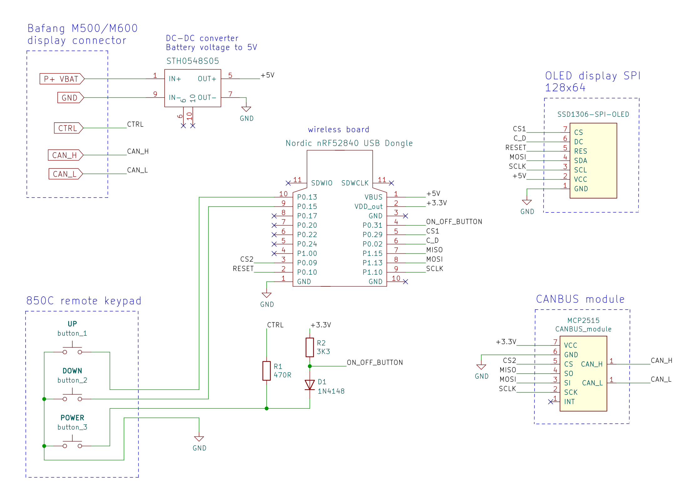
And the updated shcematic:

 
Hi! I also have the same problem, using a 1.3-inch OLED(I2C versions), the driver is SH1106, can you send me the modified driver? I don't know how to compile。 :D :D :D,My email address is ouyangdan12@gmail.com
 
ouge said:
Hi! I also have the same problem, using a 1.3-inch OLED(I2C versions), the driver is SH1106, can you send me the modified driver? I don't know how to compile。 :D :D :D,My email address is ouyangdan12@gmail.com
I did a new BETA release with that changes and others: https://github.com/OpenSourceEBike/EV_Display_Bluetooth_Ant/releases/tag/v0.20.0
 
Back
Top