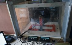
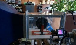
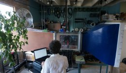
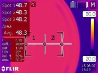
So I decided it would be a good idea to first repeat the earlier tests (see https://endless-sphere.com/forums/viewtopic.php?p=721949#p721949) that we had done using drilled vent holes in the side plates now that we have the wind tunnel to vary the wind speed, as I'd expect that the effects of vent holes with 50+ kph wind speed would be quite a bit more pronounced than when I just had an external fan blowing on the motor.
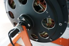
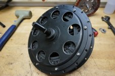
We drilled out some pretty large 1.375" (~35mm) holes around the very perimeter of the side plate, with about as much material removal as we'd be comfortable with before worrying about inadequate side plate strength. We repeated the tests first with just one side plate drilled out, then with both side covers drilled, and finally with both covers drilled and the entire insides of the motor painted black.
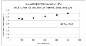
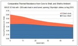
For reference, here was the test results we had with the MXUS motor and no modifications. The motor RPM's were adjusted to 10x the speed, so 200rpm at 20kph, 300rpm at 30kph etc:
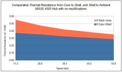
Total resistance is 0.55 oC/watt at 11kph and drops down to 0.35 oC/watt at 50 kph.
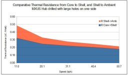
With a single side plate drilled out, the resistance went from 0.48 oC/watt all the way down to 0.22 oC/watt at 50kph. So at speeds, there was about a 60% improvement in the heat flow out of the stator.
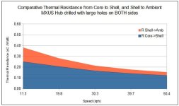
With both side covers drilled out, the results are quite a bit more striking. 0.38 oC/watt at 11kph (close to the unmodded motor at 50kph), and just 0.154 oC/watt at 50kph. That's a 130% improvement in heat conduction at fast speeds:
The addition of black paint all of the motor insides had a measureable albeit slight effect. Final resistance at speed was 0.147, compared to 0.154 oC/watt before the painting.
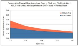
In all the above graphs, the data is still split as though the heat was flowing from stator to shell, and then shell to ambient, when this doesn't really reflect what's going on with the drilled out side plates when there is direct ambient airflow on the windings. I left it like this for modeling sake but what really matters in the end is the total sum.
The other thing we noticed was that it took WAY longer for the drilled motors to reach steady state temperature. For the unmodded motor, after ~1 hour in the wind tunnel things seemed to be in pretty good thermal equilibrium, while it typically took ~3hours to get each data point in the drilled side cover case since the side plate temperatures would drift quite slowly.
jk1 said:
awesome thread, interesting if you could compare the data with ferro fluid as well.
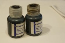


Very interesting data coming up next!


