Definitive Tests on the Heating and Cooling of Hub Motors

One idea I've been bouncing around is simply filling the gap between the windings and the shell with some heat conducting material. If you look at Justin's thermal model, the air between the stator and shell has the majority of the thermal resistance in the path. If we could reduce the path length to the minumum practial (clearance to avoid rubbing) and maximize the surface area of this gap, it may be possible to greatly increase the dissipation and still have a sealed system.
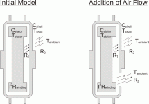
Thermal Model.gif

Oil works well because it replaces high thermal resistance air with much lower resistance oil. If the air gap between stator and shell was reduced to 2mm, the thermal resistance would be greatly reduced. The gap between the iron and magnets is already in this ballpark, so is probably the primary path for heat in a sealed hub motor. The iron and magnets don't have the best heat conductivity, but way better than air. If we added thermally conductive "filling" between the windings and the sides of the shell, leaving just a 1-2mm gap, the overall thermal resistance from copper to ambient would be greatly reduced.

From the engineering toolbox: http://www.engineeringtoolbox.com/thermal-conductivity-d_429.html

Air has a thermal resistance of 0.024 W/(m K)
Copper is 401 (16700 x air)
Aluminum is 205 (8500 x air)
Iron is 80 (3300 x air)
Magnet material 6.5 (270 x air)
Epoxy is 0.35 (14.6 x air)
Silicone oil is 0.1 (4.2 x air)

Fourier's Law are used to express conductive heat transfer

q = k A dT / s
where
q = heat transfer (W, J/s, Btu/hr)
A = heat transfer area (m2, ft2)
k = thermal conductivity of the material (W/m K or W/m oC, Btu/(hr oF ft2/ft))
dT = temperature difference across the material (K or oC, oF)
s = material thickness (m, ft)

This formula applies to a solid or non-moving fluid condition. When the motor is moving, the air (or oil) will be moving, so the thermal resistance of that path will be less.

What stood out to me is how poor a thermal conductor the magnet material is. Silicone oil is not so great either when it's not moving.

So I might try filling in the space bewteen the copper windings and the motor shell with some epoxy that's filled with powdered copper or aluminum. If I make a 2mm spacer from polyethylene or silicone rubber sheet (something epoxy won't stick to) and place it against the inside of the shell, I can fill the gap with the epoxy stuff and assemble the side and wait for the epoxy to harden. Once cured, I can remove the spacer and have a nice even 2mm gap. Repeat on the other side.

This approach would be help even with an oil cooled setup (and require way less oil).

I don't think you could apply this easily to a geared hub motor.
 
I think the limiting factor here isn't just the internal heat flow of whichever method of cooling is used, it's the interface that passes the heat into the surrounding environment. An analogy would be a motorbike engine where both systems can be found. Both work but if the engine doesn't get adequate airflow it will overheat. The liquid cooled engines will have a fan fitted to aid cooling where needed- thermostatically controlled and electrically powered. So- perhaps not easy but why not have an externally mounted fan to aid heat flow away from the motor? Ducting to direct air over the motor? Perhaps not easily mounted or aesthetically pleasing - has anything been tried in that area?
 
Fechter,

You really can't look at the heat transfer through the air inside a sealed hubbie as conductive transfer unless the motor is stopped, but even then there's still a portion through radiation and a bit of convection. When stopped the shortcomings of conduction through air becomes readily apparent with such long cool-down times.

The motors I use are about as close as you can get with being full as you can get, with drastically less enclosed air than common hubbies (the effect you're after with the mods you mentioned), but the difference in heat transfer is relatively small.

During operation convective heat transfer is dominant, and that goes for oil fill as well as plain old air. It's a good that it's through convection because it's the easiest to improve upon, because the manufacturers do a piss poor job of addressing it. The convective heat transfer coefficient using air and a solid can vary pretty dramatically http://www.engineeringtoolbox.com/convective-heat-transfer-d_430.html, however, the effect of changes that improve the convective heat transfer inside the motor whether it's using air or oil or some other fluid will be limited without changes to the outside shell of the motor. Claiming otherwise is essentially saying that the outside surface of a stock sealed hubbie can't get quite hot. We can do some things outside that make relatively small improvements to the convective heat transfer coefficient from the exterior surface to the air outside, but the real opportunity for improving heat transfer is by significantly increasing the exterior surface area, and if you're sticking with air inside, then you need to increase the surface area inside the motor shell too.
 
John in CR said:
Fechter,

You really can't look at the heat transfer through the air inside a sealed hubbie as conductive transfer unless the motor is stopped, but even then there's still a portion through radiation and a bit of convection.

Exactly. The barrier to heat flow from stator to shell is not the heat flowing through the air, rather it's the junction of it moving from the stator TO the air, and then from the air TO the side covers. Internal turbulence will keep the air temperature inside the hub relatively uniform throughout. If it was conductive transfer instead, then there would be a steady temperature gradient in the air from the hot stator to the cooler side plates.

If one is attempting to encourage air circulation for cooling I'm not sure if a smaller gap between the stator and rotor would help or hinder in that regards, since my intuition tell tells me that a larger gap could allow for more total mass flow of air in the region, but perhaps the tighter proximity is more beneficial. Does somebody else with more active experience have an idea on that?

It's funny though because that is what I keep thinking too. If only there was a way to move this heat from the stator to the large side plates, like some kind of "thermal brushes" which would conduct from the stationary windings to the moving shell. Liquids of course do the job perfectly, but are such a messy PITA to work with in practice, especially in retrofitting existing motors that were not designed from the ground up with oil sealing in mind.

and if you're sticking with air inside, then you need to increase the surface area inside the motor shell too[/b].

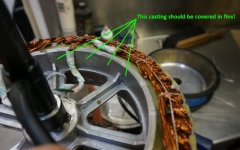
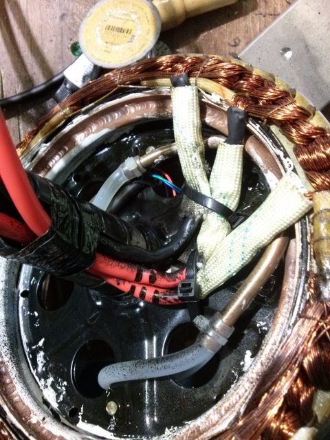
THAT is something that I've never seen mention of but you are totally right. There is talk and practice of putting vanes inside the shell to increase turbulence and airflow, but not so much in the context of increase surface area for convective heat transfer. And I've never seen (but correct me if I'm wrong) someone putting fins on the motor stator to help heat shed from the stator to the air in the hub. But there is a ton of space on the insides of stator core to fit this. Here's the insides of the MXUS stator, they could literally line the insides of the core casting with fins and get a much more massive area for convective heat transfer to the inside air.
PotentialFins.jpg
 
Where you pinpointed the location for heat sinks is where Linukas did put his water cooling loop.

oKOeGFjl.jpg
 
Adding features to the stator support and inside & outside motor covers to increase surface area will help with air as the transfer medium inside the motor. It may well be enough for an average-power motor, which would be great as it's simple and passive = reliable and cheap.

But if air isn't up to the job (say for a high-power motor) I just can't shake the feeling that an oil bath is the answer and the answer is to bite the built and modify the design of the motor to allow effective sealing. Then you'd only need to feature the outside of the motor covers, where dissipation would still be limited by the air interface.

Or maybe the true answer is to increase efficiency of the motor so it produces only a small amount of waste heat that can be easily dissipated by passive air cooling in a sealed design...
 
Well while we wait for more efficient motors we might as well play around with what we got as of today. There have been a few builds with the use of oil cooling of motors here, even the pikes peak winning trike. But it seems all struggles to keep oil inside the motor. A few even tried to drill a hole to avoid pressure build up. But AFAIK they are still adding oil on a regular basis. Oil probably is the most effective cooling method today, but not the cleanest. Meaning an oil dripping hub might not have a huge WA factor.

I wonder how much oil they need to refill over the year? Maybe other liquid that don't stain could be used? What about that 3m non conductive liquid? Been used for cooling over clocked computers and worked well. I know it is expensive but how much would be used over a year? Hm come to think of it, maybe that liquid would vaporize as it heats up and vanish as gas?

What is great about oil cooling is the ease of the mod, and the cost. And if one can live with some oil dripping I guess nothing else will come close to oil cooling.

Is there a way to seal a motor to avoid dripping? Probably not as I have read in them other threads about the topic. Seems even hull completion on ships are not possible to seal 100%. And my guess is that in the shipping industry they might have looked into that a time or two.
 
macribs said:
Is there a way to seal a motor to avoid dripping? Probably not as I have read in them other threads about the topic. Seems even hull completion on ships are not possible to seal 100%. And my guess is that in the shipping industry they might have looked into that a time or two.

On the subject of sealing, back when I was a lot more excited about oil fill we spent a lot of time looking into bearing isolators rather than physical shaft seals. This is a clever active technique where you have spinning baffles almost that keep deflecting water back out of the motor and keep deflecting the oil to stay in, and it does it with no additional drag(Large dia. rubber shaft seals do not spin very freely!) and it intrinsically allows for pressure equalization inside and outside the hub. Have a look:

http://www.inpro-seal.com/en_US/system-and-bearing-protection/permanent-bearing-protection/

[youtube]Lr7hlo890eA[/youtube]

They seemed like the ideal solution but unfortunately samples are $$$ and when we looked at getting production volume quotes of units sized for a hub motor application, the BOM cost of the bearing isolators was more than all other motor components combined.
 
justin_le said:
On the subject of sealing, back when I was a lot more excited about oil fill we spent a lot of time looking into bearing isolators rather than physical shaft seals. This is a clever active technique where you have spinning baffles almost that keep deflecting water back out of the motor and keep deflecting the oil to stay in, and it does it with no additional drag(Large dia. rubber shaft seals do not spin very freely!) and it intrinsically allows for pressure equalization inside and outside the hub. Have a look:

http://www.inpro-seal.com/en_US/system-and-bearing-protection/permanent-bearing-protection/


They seemed like the ideal solution but unfortunately samples are $$$ and when we looked at getting production volume quotes of units sized for a hub motor application, the BOM cost of the bearing isolators was more than all other motor components combined.

Can't get the video to play but will check their website. Would the inpro seal be mounted on the inside of the side cover or pressed on the axle itself?

Do you remember what price quote you got? If price is not insane it could still make sense to have a go. Combined with some heat sinks for added mass the result could turn out great. After all, all cooling mods will costs money. Some mods more then others. But not all cooling mods will remove significant amount of heat. Heat sinks and oil will.
 
Rather than the cooling loop on that V1 mxus above - we should make the whole stator solid aluminium with a large surface area!

And the V2 mxus was born...

Sam.
B.Eng (Mech)
 
Those bearing isolators do look good, but if they are too costly there must be a traditional rubber lip seal that would have an acceptably low drag (compared to a typical 1000W DD motor) and accept it as a compromise. They are at least only a splash seal.

I guess phase/hall connections would require potted connectors in the axle - might be awkward fitting it all in around the axle circumference.

A separate breather of some kind would be required.

I think there are a lot of potential solutions that could be borrowed from the automotive industry.
 
Samd said:
Rather than the cooling loop on that V1 mxus above - we should make the whole stator solid aluminium with a large surface area!

And the V2 mxus was born...

Sam.
B.Eng (Mech)

Hehe I give you partial credit for that one ;)
But as big as the new solid stator is - water still removes more heat faster.
 
No argument from me.
Its just so hard to get it to cook though.
Screenshot_2015-07-21-18-37-16.png
 
Good point Justin on the fin area for better heat transfer from coil /back iron. Another green field option would be to have many more ribs (Spoke style)connecting the stator center and have the left side of the stator support double as the outer cover on the left side and supported with 3 smaller planet bearings. You could vent the center or do a host of different cooling options.

Oil is a good cooling medium in higher temperature applications, but in these lower temperature range apps, water has significantly higher heat transfer. Just add some glycol if you run winter time.
 
How about if the stator had concentric 'fins' along the sides and they intermeshed with fins on the inside of the covers.
Hard to explain without a picture, but they would look like a series of rings centered around the axle. Ones on the covers mesh with the ones on the stator but have just enough clearance to avoid rubbing. This would increase the surface area for heat transfer.

Yes, I know a static situation is much different than with air flow, but the air part is still the highest resistance. Shortening the path and increasing the surface area will both help. If the air gap is really small and the two surfaces are moving with respect to each other, you will have some kind of very short path circulation between the two sides. Anything that disrupts the boundary layer against the metal will increase heat transfer.

On the outside, if you are travelling at 'normal' speeds, the ambient wind does a pretty good job of removing the heat. If I ride up a hill, stop at the top and immediately feel the motor, it's not that hot. If I wait a minute or so, it gets much hotter as there is no more wind cooling the outside.
If that's not good enough, adding fins to the outside is relatively easy. Simply machining the covers with shallow grooves could easlily double the surface area without needing more aluminum.
 
justin_le said:
On the subject of sealing, back when I was a lot more excited about oil fill we spent a lot of time looking into bearing isolators rather than physical shaft seals. This is a clever active technique where you have spinning baffles almost that keep deflecting water back out of the motor and keep deflecting the oil to stay in, and it does it with no additional drag(Large dia. rubber shaft seals do not spin very freely!) and it intrinsically allows for pressure equalization inside and outside the hub. Have a look:

http://www.inpro-seal.com/en_US/system-and-bearing-protection/permanent-bearing-protection/

They seemed like the ideal solution but unfortunately samples are $$$ and when we looked at getting production volume quotes of units sized for a hub motor application, the BOM cost of the bearing isolators was more than all other motor components combined.

Justin came to think of what I read in one of the oil cooling threads. Pressure build up inside the hub as the oil heats up. Think those inpro-seals handle that as well?
 
speedmd said:
water has significantly higher heat transfer. Just add some glycol if you run winter time.

That, and a whole lot of corrosion inhibitors for the mix of aluminum, copper, steel, and rare earths it will be in contact with!

macribs said:
Can't get the video to play but will check their website. Would the inpro seal be mounted on the inside of the side cover or pressed on the axle itself?

Hopefully you got to play the video OK since it's pretty neat. Typically this would be on the outside of the side cover, so that the bearing is in on the oil filled side. The only potential issue I saw was that all the examples are for spinning shaft devices, where centripetal forces are playing a role in sending the contaminants back out on each side. I'm presuming they could engineer one just as well for a spinning hub and a static shaft, but I don't recall seeing examples of this.

Pressure build up inside the hub as the oil heats up. Think those inpro-seals handle that as well?
Since they are a contactless device I was under the full impression that air could move back and forth effortless to equalize pressure. That's a huge part of the reason why I thought they'd be perfect for this. Once you have a rubber shaft seal, then you need some kind of explicit vent to let air in and out, and a vent that lets air flow but doesn't let oil out or water in is another tricky one. Though it looks like there are some oleophobic gore vent products that will work with both fluids OK
http://www.gore.com/en_xx/products/venting/packaging/pack_vents_oleo_vs_hydro.html

Do you remember what price quote you got?
For something that would fit with our 45mm bearing designs we were looking at ~$400 for samples and ~$130 each in the 100 pcs quantity. The thing is the part itself has the appearance of being readily machinable on a CNC mill or lathe, and so if you really understand the design principles it might be possible to manufacture this part in house or design it right into the side covers and axles. It's just for us we have more than enough R&D on the plate to take something like this on something like this too.

Punx0r said:
Or maybe the true answer is to increase efficiency of the motor so it produces only a small amount of waste heat that can be easily dissipated by passive air cooling in a sealed design...

I'm all for improved efficiency, but while you can readily improve the peak efficiency by minimizing core losses with thin laminations + better grade steels, the main sources of heat at loads that are overheating hubs comes from the copper losses when running at high current. The difference bewteen a 92% peak efficiency motor and an 80% peak efficiency is of no consequence in this regime. For a given motor kV, you need a given amount of amps through the phases windings to produce a required torque, and you can only reduce the R term of I^2R as much as the material limitations of copper and the mechanical space constraints for fill factor allow.

It's not quite like batteries were you can simply source power cells that have like 80% less internal resistance than normal cells, though that would be sweet if there was a metal alloy out there with 80% less resistance than copper wire.

fechter said:
How about if the stator had concentric 'fins' along the sides and they intermeshed with fins on the inside of the covers.

Funny that was also just the picture I was envisioning in my head too. Without doing FEA models of the air flow it's hard to say what precise benefits might or might not come from clever inter-meshing fins but it's hard not to imagine this having a positive effect. If we could get the overall heat transfer from stator to side plates some 2-3 times better than it is by at current with _zero_ design optimizations, then that would be almost as good as an oil fill solution.

The main barrier to heat flow at that point becomes the side plates to ambient. Some wind tunnel tests coming fairly soon to quantify/characterize that.

-Justin
 
That's an interesting idea. The large increase in surface area would be of obvious benefit for transferring heat, but the intermeshing might improve distribution of the hot air over the full area of the "cold" side fins. An non-meshing, high surface area option might be two opposing pin-fin arrangements which might suffer from a lack of hot air flow down to the roots of the cold side pins. CFD would be useful if anyone has access to it?
 
Man I like the way this thread is going, feels like something great will be the end result.
Great reading about venting.
 
speedmd wrote:
water has significantly higher heat transfer. Just add some glycol if you run winter time.
That, and a whole lot of corrosion inhibitors for the mix of aluminum, copper, steel, and rare earths it will be in contact with!

Was suggesting water use only captivated in tubes or core cavities as done in piston engines. Most standard coolant mixes are fine with metal mixes short term at least.

Wondering if any wheel hubs currently in use have a open side. I could see one being possible with a double row bearing holding steady a sturdy side plate. You would be free to leave as much area as you wished for cooling on the opposite side and even have a removable -partial dust/ debris shield to protect windings and other items.
 
Guys i tought that you would appreciate if i make a video about IR thermal radiant reflection from different surface in relationship of emissivity and help you to understand that IR thermometer will give you results that will vary and might be wrong if you dont understand emissivity concept and use the right surface to measure!

My understanding is that side cover that have inside surface in bare aluminum will reflect the radiant heat from the stator and it will bounce back to it, contributing to keep high temperature. However if the inside surface of the side cover are absorbing radiant heat, the side cover will better transfer heat to the exterior of the motor. As well like Justin Tested, the heat radiated from the stator to the side cover represent only few % but i think if this can allow you few more dozen watt to drive the motor at, i think it might worth 8)


Reflectance test of various surfaces: Bare aluminum, Black anodized aliminum, Ordinary black paint aluminum and High Emissivity Krylon 1602 paint.

Enjoy!

[youtube]5FYBeIwjG90[/youtube]
 
Thanks for the video Doc! It would be interesting what happens at higher temperatures for instance at 80°C and 120°C.
Will the black anodozing still be almost as good as the krylon, or does it become worse. What do you think?
 
madin88 said:
Thanks for the video Doc! It would be interesting what happens at higher temperatures for instance at 80°C and 120°C.
Will the black anodozing still be almost as good as the krylon, or does it become worse. What do you think?

Inside the covers and outside the covers you ideally want 2 different selective coatings. On the inside you want to absorb infrared heat but not emit it back at the stator. On the outside you want to emit heat but not absorb it from the environment, especially if it's subjected to direct sunlight. Common black paints won't be good at either, because they are generally absorb and emit well, though I did find a BBQ once that claimed to be selective with lower emissivity to keep more of the heat inside your BBQ pit when you paint it on the outside.

There are some specialized coatings for the solar industry that would work well. There's a nice list here http://www.solarmirror.com/fom/fom-serve/cache/43.html.
 
Justin,

You've become jaded by common low efficiency hubbies. Except briefly in the early part of acceleration I enjoy the 90% and up range of efficiency. While I need at 15kg motor to haul my load and meet my performance demands, there's absolutely no reason the same design can't be scaled for ebike use and achieve real efficiency.
 
Back
Top