Eastwood’s first battery build

You can use a low current bms and bypass it on discharge, but let it control the "on" wire on the controller and the dc-dc converter for the contactor. That way you still have LVC and protection if a single cell group goes low (or high).
Interesting, thanks for replying. Im slowing starting to understand the BMS aspect of this battery build. To me, the actual battery build seems more simpler than figuring out the BMS 😅

With a higer current bms you can move the shunt so it senses the current even though it is bypassed, like I do on the yamaha. Then it can still cut on overcurrent and show relevant currents and SOC.

I was just looking at your recent post on this, trying to make sense of all of this. Thanks for posting the steps on how you did this, in your Yamaha thread.
 
Alternately:

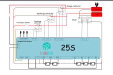
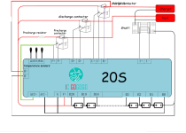
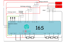
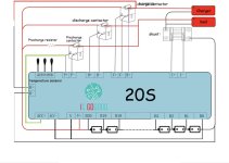
What do you guys think about something like this? I should’ve showed in the diagram, I’m bypassing the BMS for the discharge, so, just ignore the wires coming from the BMS.
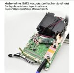
If you use a contactor based BMS, then you have no need to bypass the BMS for discharge (so the BMS can still protect the cells against damage even while riding, not just during charge), because you can drive the contactor with the BMS, so that the system will shut off from either the BMS or the keyswitch, etc. I know there are some of them posted about here and there, I think from JBD, but can't remember for sure.

You can also DIY a contactor-drive from the BMS, so you can use a low-current BMS, yet still not have to bypass it for discharge. There's at least one thread about that around here somewhere....


Note that if you bypass the BMS for discharge, without any way for it to stop the system from discharging when a cell group reports a problem, you could damage cells (or worse).
 
Alternately:


If you use a contactor based BMS, then you have no need to bypass the BMS for discharge (so the BMS can still protect the cells against damage even while riding, not just during charge), because you can drive the contactor with the BMS, so that the system will shut off from either the BMS or the keyswitch, etc. I know there are some of them posted about here and there, I think from JBD, but can't remember for sure.
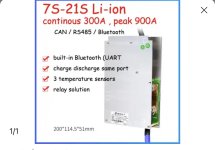
But is there a “contactor based BMS” that can handle 850 phase amps and 450 DC amps?? The highest discharge BMS I have been able to find is 240 A continuous but that’s not a contactor BMS..

You can also DIY a contactor-drive from the BMS, so you can use a low-current BMS, yet still not have to bypass it for discharge. There's at least one thread about that around here somewhere....
If you stumble across that thread, please post. I don’t know why but the search function on this form doesn’t work well with me. I’m sure it’s me tho 😅


Note that if you bypass the BMS for discharge, without any way for it to stop the system from discharging when a cell group reports a problem, you could damage cells (or worse).
Yeah for sure don’t want that. I want this battery to be safe as possible with using Li-ion.
 
But is there a “contactor based BMS” that can handle 850 phase amps and 450 DC amps??
Again, phase amps are between the controller and the motor. The BMS does nothing with phase amps, you can ignore them for the purposes of sizing your components. In fact, you basically have no control over phase amps: whatever motor you're using already has the 3 phase wires built into it, you will not (easily) be able to change the gauge of those cables.

And if you DIY a BMS-controlled contactor, then whatever your contactor is rated for, that's what how much battery amperage you can handle.

If you stumble across that thread, please post. I don’t know why but the search function on this form doesn’t work well with me. I’m sure it’s me tho 😅
I did link it earlier:
It was my thread actually, and you've reminded me that I was meaning to sketch out a basic diagram for DIYing it without having to purchase a pre-made contactor-based BMS. I just posted on that thread with a quick sketch of what to shoot for.
 
Again, phase amps are between the controller and the motor. The BMS does nothing with phase amps, you can ignore them for the purposes of sizing your components.

Yes, I understand that the phase amps are between the controller and motor but from my understanding the more phase amps used, the more amps are pulled from the battery. I’ve seen this discussed before on ES, but can’t find the topic. The controller can’t just produce 850phase amps without pulling more current from the battery. If I’m pulling 850 phase amps it going to pull more current from the battery for short periods. That’s why I asked if the conductor-based BMS set up could handle that much DC current and phase amps without shutting down the BMS.


In fact, you basically have no control over phase amps: whatever motor you're using already has the 3 phase wires built into it, you will not (easily) be able to change the gauge of those cables.

you say we have no control of the phase amps based on the wire size?? I’m not sure where you’re getting that from my friend. We definitely have control over the phase amps based on the controller setting. Obviously thicker wires would be more efficient but the stock phase wires are not going to stop the phase amp setting in the controller.

Also it’s not that hard to change phase wires my friend. I’ve done it on several motors. I’m consider doing it on this build using the QS 138, but not now, probably will down the road if needed. First Need to see what type of temperatures I’m working with after putting it through some hard Enduro riding.

In fact, changing the phase wires on a mid drive is much simpler than doing it on hub motors and trying to squeeze those wires through the axle.

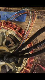
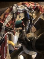
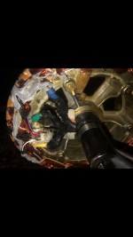
Here’s a couple pics of 6 AWG wire through the axle of a QS 205 I did several moths back 👇


And if you DIY a BMS-controlled contactor, then whatever your contactor is rated for, that's what how much battery amperage you can handle.


I did link it earlier:

Yes, I have read your topic several times, still soaking in the information 🤓
 

Attachments

  • E40F54FF-BE3B-474B-B491-DA3848F5C2E7.png
    E40F54FF-BE3B-474B-B491-DA3848F5C2E7.png
    10.7 MB · Views: 13
  • D7E620A1-7EF2-4802-81D1-334BBCE5F661.jpeg
    D7E620A1-7EF2-4802-81D1-334BBCE5F661.jpeg
    636 KB · Views: 12
  • 27A63766-27D0-4C52-B785-EAD677CD4C00.png
    27A63766-27D0-4C52-B785-EAD677CD4C00.png
    5.2 MB · Views: 12
But is there a “contactor based BMS” that can handle 850 phase amps and 450 DC amps??
No, because the BMS (or contactor) doesn't handle phase amps. Only the controller deals with that.

The BMS and contactor only see battery amps.

It makes no difference what your phase amps are or what they peak to--whatever the controller is setup to limit battery amps to is what it will do (assuming it's settings are actual and not some approximation or whatever because of crappy programming), and so the BMS, battery, contactor, etc will only see up to that limit.

If your controller is setup to limit battery amps to some specific amount, then assuming it's correctly designed and the software is properly written, that will limit the phase amps you can pull, even if you set the phase amps higher than that, becuase the battery current limit is there to protect the battery from damage.

If you have a controller that can decide to violate the battery current limit to get you more phase amps, it's not designed properly, because it can't protect your battery like it is supposed to. (the BMS is really emergency protection, a last ditch line of defense against a problem with your ysstem, to prevent cell damage that can lead to a fire. If the systme is correctly setup and designed it will never allow current draw, etc., that could even get close to the limits of the battery under worst-case conditions).


The highest discharge BMS I have been able to find is 240 A continuous but that’s not a contactor BMS..
The whole point of a contactor based BMS is that you are limited only by which contactor you use. The BMS does not handle the current, your ocntactor does. The BMS just controls teh contactor.

I think the ones I have seen posted about were by JBD, so you might look at their stuff to find one. Even if they don't come with a high enough rated contactor you can use your own instead, as long as it has the same coil ratings as the ones they use.

A quick google finds some references:
JBD contactor BMS - Google Search but I didn't read thru them, just skimmed the google summary page for a few seconds.

Or as noted, you use a generic low-current-capability (doesn't even need to handle a few amps) BMS, and use that to control a contactor of your choosing. (see the stuff already posted about DIYing this).

I don’t know why but the search function on this form doesn’t work well with me. I’m sure it’s me tho
No, it's the search. ;) It'll get upgraded at some point, depending on Neptronix's time / scheduling / availability; it's probably going to be a while, though.

In the meantime you can search for anything posted before the forum switchover using the archived version of the old forum here:
it at least will find much more content than this version does. WOn't find any stuff posted since the conversion, though.
 
Last edited:
Seems like it should work. :)

I would bet that the other one would work, too, if purchased without contactor and using whatever one you want to use for the whole system (or just swapping out the contactor it comes with for yours), as long as the shunt in the BMS can be swapped out for a higher current as well, and/or the settings in the BMS changed to use your own shunt.
 
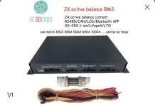
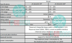
BTW, these are the specs for the JK BMS off that page, for reference in future if their ad chagnes or goes away.

I wonder which "MOS" (FET) they are monitoring for overtemperature, since it is using contactors not FETs for the current path?

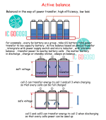
It is also an "active" balancer, using capacitors to shuffle charge around, so it could theoretically balance at any voltage whether you're charging or not (if it's software allows that).


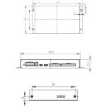
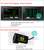
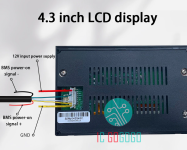
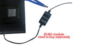
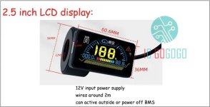
LCD display , CAN chip , RS485 Module , LCD displays don't include in BMS , need to buy separately !

can match 100A 300A 500A 600A 1000A ......and so on relays

Overview:


JK-B2A25S-RP battery management system is a battery management system tailored for large-capacity series lithium battery packs. The system is suitable for battery packs of 3S to 25S, and has the functions of battery protection, voltage acquisition and voltage equalization.

The balance function of the system uses super capacitors as the medium to achieve active energy transfer balance. When the system is working, it realizes battery protection functions such as overcharge, overdischarge protection and short circuit protection, and transfers energy with a balancing current of up to 2A continuously. The balancing current does not depend on the voltage difference of the battery cells in series in the battery pack. The voltage acquisition range is 1V~5V, and the accuracy is ±3mV. External communication interface can choose RS485 bus, CAN bus, GPS interface or LCD interface. It can be applied to all types of batteries on the market such as lithium lifepo4, li-ion lithium, LTO ,Lipo, and lithium lead acid.

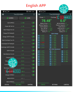
The system has Bluetooth communication function and is equipped with mobile APP software. You can connect the device system through Bluetooth to check the voltage of the single battery, check the balance status, and modify the setting parameters. It can be used in battery packs of small sightseeing cars, scooters, forklifts, shared cars, high-power energy storage, base station backup power, solar power plants, etc. It can also be used in battery balance maintenance and repair.


Main Specifications
◆ Support 3S to 25S battery packs;
◆ Overcharge, overdischarge voltage protection and overcurrent protection parameters can be set through APP, with short circuit protection function;
◆ Real-time, active balancing, balancing current 2A, voltage difference between batteries after balancing ≤5mV; ◆ Reserved charge/discharge and precharge switch control interface (12V), equipped with 500A current shunt (75mv);
◆ Support 3 temperature probes;
◆ Single voltage range 1V ~ 5V, accuracy ±5mV;
◆ With coulomb counter function;
◆ Suitable for large capacity ternary, lithium iron, lithium titanate and other lithium battery packs;
◆ Bluetooth communication function, equipped with APP, can check the status of the battery in real time;
◆ Support external interface RS485, CAN bus, GPS interface;
◆ Low voltage shutdown function to prevent battery damage;
◆ Heating function;
◆ Support weak current switch (display interface activated);
◆ Support ACC ignition switch;
◆ Relay driving voltage: 12V, 24V, external (maximum 84V), standard 12V;
◆Operating temperature range: -20℃~70℃;
◆Power requirements: 16V~100V, can use battery self-powered or external power supply.
◆Power consumption: the maximum power consumption of the protection board is 1.5W (excluding the power consumption of the relay), and the power consumption of the shutdown is 20mW.

1 Cell undervoltage protection: Lifepo4 2.500V ; li-ion 2.800V
2 Single-cell undervoltage protection recovery: Lifepo4 2.650V; li-ion 3.200V
3 Cell overcharge voltage: Lifepo4 3.65V; li-ion 4.2V
4 Cell overcharge protection recovery: Lifepo4 3.6V; li-ion 4.1V
5 Trigger equalization dropout: 0.01 V
6 Automatic shutdown voltage: Lifepo4 2.5V; li-ion 2.799V
7 Charging overcurrent protection current: 100A
8 Charge overcurrent protection delay: 30 seconds
9 Charging overcurrent protection release time: 60 seconds
10 Discharge overcurrent protection current :400A or other current , depends on the relay you use
11 Discharge overcurrent protection delay: 30 seconds
12 Discharge overcurrent protection release time: 60 seconds
13 Short circuit protection release time: 60 seconds
14 Charging over temperature protection temperature: 70 ℃
15 Over-temperature recovery temperature after charging: 60 ℃
16 Discharge over-temperature protection temperature: 70 ℃
17 Discharge over-temperature recovery temperature: 60 ℃
18 Charging low temperature protection temperature: -20 ℃
19 Charging low temperature recovery temperature: -10 ℃
20 MOS over temperature protection temperature: 100 ℃
21 MOS over temperature protection recovery temperature: 80 ℃
22 Number of series: 3S~25S
1681854366714.png
1681854406047.png
1681854387098.png
1681854460421.png
1681854481903.png
1681854493815.png
1681854507581.png
1681854533812.png
1681854552801.png
1681854571197.png
 
Last edited:
I have 3 JKBMS in service currently, one on the motorcycle, two for stationary solar powerwalls. The bluetooth range kinds sucks and is easily blocked by a piece of wood or a corner, so the screen is a good idea, but i wouldn't think it'd be necessary on the handlebar or anything visible while riding. You'll want voltage and current draw easily viewable during a ride, but all the other info, in my opinion, isn't important mid-ride. I played around with detailed setting for a couple months via bluetooth, but then I got everything dialed in and I now rarely pull up the app for the motorcycle's BMS data or change setting.

I have intentionally and unintentionally (whoops!) tested all of its protection settings, they all worked for me, in all 3 applications. I like having 3 of the same BMS because i use 1 app on my phone and I can monitor all three of my batteries from the same app. Not at the same, obviously, it's not like split screen. Online, i have found some reported failures, but the price isn't bad. Off-Grid Garage on YouTube even sorta intentionally discharge a battery at max current and one of the FETs in the JKBMS popped, but the rest of the unit still continued to work. Neat.
 
I have 3 JKBMS in service currently, one on the motorcycle, two for stationary solar powerwalls. The bluetooth range kinds sucks and is easily blocked by a piece of wood or a corner, so the screen is a good idea,

Good to know about the Bluetooth range 👍
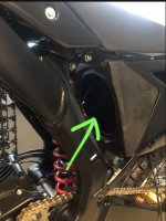
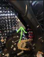
I’m hoping I could fit this bms on the bottom side of my gutted gas tank. Which would be directly on top and or above the battery.

For fitting the contactors, they could fit inside the airbox, although I plan to put the controller inside the airbox.

098D8675-2E9B-45EC-87DF-E4D1999BF7BC.jpeg

Or better yet, I can make a separate compartment behind the “battery box” above the motor for the contactors, plenty of room back there.
Just speculating on design ideas 💡🤓
9CD67062-638D-42DF-B758-263F6F798FD6.jpeg
 
Yeah good question! Maybe harrisonpatam knows..
Unfortunately no, because all the JKBMS's that I use are the FET-only variety, sub 200A, I'm not using a contactor BMS.

Consider my comment from a few days ago: I'm not sure how much you'll actually end up using more than 200 amps on a regular basis. With that understanding, know that one of the settings for JKBMS that you have control over is over current protection delay. Meaning, you can get a 200 amps JKBMS, no contactor, and pull more than 200 amps for a couple of seconds here and there, before the overcurrent protection engages and shuts off discharge. When you do that, you of course risk the BMS's FETs. But you could potentially be fine 95% of the time, and have short 2-second 300 amp pulls here and there. Amberwolf will be more knowledgable than me regarding the hard and soft limits of FET's, and how much of a risk it actually is to exceed their current rating for short bursts. I can only offer that I have my 200amp hard limit, with a 3 second delay, and I never even really break 150amps on a 350 pound cruiser.

Just something else to consider for the build. If you were starting to get overwhelmed by the contactor-based BMS.
 
The below is generally true of any device using FETs as on/off current switches that aren't PWM'd (not controllers, for instance) but just left on all the time and only turned off when commanded (devices that PWM them or switch them on and off quickly or often have other limitations that can require a higher capability FET than otherwise):

If the FETs themselves are rated for higher current, then assuming the heatsinking and heatshedding ability of the BMS in whatever enclosure it is in is sufficient to allow that without overheating the FETs, then you wouldn't be actually running hte FETs over limit, so they should be ok,, assuming the design of the drive circuit is good enough to actually turn them on fully. (partly turned on FETs have much higher resistance and so they heat up way faster).

If the FETs are not actually rated for the current you want to put thru them, then every overcurrent event is a risk of damage--it could just cumulatively damage them until they eventually pop, or it could just blow them right then.

If the FETs are rated for the current but heat can't get out of them fast enough for whatever reason, then the problem is the same.


A BMS could be rated for a certain current but actually be capable of more; you'd have to find out from the manufacturer how they generate their ratings.

Keep in mind a proper rating will include a large safety margin (25-50%) to ensure no failure will ever occur because of such damage...but most of the parts we see for DIY EVs have NO safety margin, or are actually used beyond at least one of the parts' specification limits for any particular device. (batteries themselves are a good example of this, with cell ratings vs pack ratings, etc).
 
Consider my comment from a few days ago: I'm not sure how much you'll actually end up using more than 200 amps on a regular basis.

For some of the more Extreme stuff like hard Enduro, I’ll need 250-ish DC amps or more. I ride in the mountains and have some extreme hill climbs that require lots of power to get up. Other times I’ll definitely have the DC amp set to 450a to play around on. I’ve always been an acceleration junkie, so I’ll be using more than 200amps on a regular basis.

Also considering at 17 groups of parallel that will give me a max discharge of 765amps which I’ll never use, but I would definitely take up to 450a at times., which is 26amps per cell group which isn’t pushing the cells anywhere near their max output of 45amps, or the conservative rating of 30amps per cell group.

On my current build, I run 150 dc and 350 phase for off road and some of the hill climbs have to avoid because it’s not enough power. Also, considering my current bike is only 160 pounds and this is gonna be more like 250lbs so I’ll need more DC amps to overcome the weight plus I need more horsepower in general. Aiming for around 35-ish Horse power when at 450 dc amps. I’ll be putting this bike on the Dyno to see what type of horsepower and torque output to the wheel.


Just something else to consider for the build. If you were starting to get overwhelmed by the contactor-based BMS.

Yeah, good point, was considering that 300 amp continuous BMS to keep things more simple without a contactor based bms, BUT know I want to play with more power than that. So I’ll end up going with a contactor based BMS. Thanks to your help and Amberwolf, I have a much better understanding of how these “contactor based BMS”set up’s work now 😀

Edit: video below. That’s not me in the video, nor is it my video. Just an example of the power requirements I need for the type of riding I do at “Brushy Mountain motorsport park“
 
Last edited:
I'm not sure how much you'll actually end up using more than 200 amps on a regular basis.

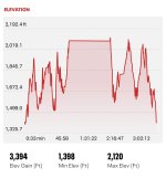
Here is the elevation chart of my last ride on my current build.

DFAEAB59-067E-4F15-AB3D-795461D4254C.jpeg
Also, considering that’s not even the extreme stuff, that’s just the basic trail loop. The Black diamond enduro trails have even steeper hills, which I’m looking forward to with this new build 🤠

 
Hi Eastwood,

It is your project and I’m not here to tell you what to do it’s your choice and your project. Battery pack are measured in Watts-hour like J Bjork said and he has build a really powerfull motocross. For your question about the throttle modulation the answer is no, not with a Fardriver controller because you can program the max RPM regardless of the voltage pack you used. If your max rpm is 6500 at 72 Volt you can program the same 6500 RPM Max at 100 volts then the modulation of your throttle at all speed will remain the same.

Or you can use a bigger rear sprocket to do this job with to get the same max rpm for the rear wheel. this way you have more torque at all speed and your top seed remain the same of a 72 Volt system. And the funny part ... your throttle will be more responsive, you will accelerate faster and the throttle is more accurate this way and you can also asjust the response for the throttle with a Fardriver for your needs the choice is your.

If this second option gives you too much torque for your need you just have to drop the battery amps a bit and your phase amps a bit until you find the correct line amps and phase amps for your need with your electric motocross, Bluetooth Fardriver apps is easy to use even on a trail. Sorry i'm blonde i just saw the click on me later on lol.
 
Last edited:
Hi Eastwood,

It is your project and I’m not here to tell you what to do it’s your choice and your project. Battery pack are measured in Watts-hour like J Bjork said and he has build a really powerfull motocross. For your question about the throttle modulation the answer is no, not with a Fardriver controller because you can program the max RPM regardless of the voltage pack you used. If your max rpm is 6500 at 72 Volt you can program the same 6500 RPM Max at 100 volts then the modulation of your throttle at all speed will remain the same.

Or you can use a bigger rear sprocket to do this job with to get the same max rpm for the rear wheel. this way you have more torque at all speed and your top seed remain the same of a 72 Volt system. And the funny part ... your throttle will be more responsive, you will accelerate faster and the throttle is more accurate this way and you can also asjust the response for the throttle with a Fardriver for your needs the choice is your.

If this second option gives you too much torque for your need you just have to drop the battery amps a bit and your phase amps a bit until you find the correct line amps and phase amps for your need with your electric motocross, Bluetooth Fardriver apps is easy to use even on a trail. Sorry i'm blonde i just saw the click on me later on lol.

Yeah, you all have convinced me to go with the higher voltage! 😀
I replied to your other comment as well in the other tread, I’m thinking I will go with 28S. Thank you for your input!
 
Well, since I’m going with higher voltage now, might as well go with 30s and use the CL700(126v) controller made by SHUL motors. Seems like it’s our best option for controllers. Does anyone have suggestions for a 30s BMS?

 
Waiting to order the cells as they’re out of stock.

So I was wondering, if I build a battery pack that’s going to have 330 cells, (30s 11p) how many extra cells should I buy to account for cells that have higher internal resistance, self discharging cells, etc. etc.??? Basically cells that are not evenly matched with the other ones that will not be a part of the battery pack.

I was thinking of buying an extra 10 cells, is that enough?
 
10 is good. You're presumably getting new ones, its possible you could order 330 and get 330 good ones. 10 is insurance so that if you get 2 bad ones, you don't have to reorder or return. And id say if you order 340 cells from a reputable source, and get more than 10 bad ones, you're due for some free cells from that seller.

And if you have 9-10 extra decent cells after building your battery, make a powerbank or UPS or something.

Yeah hoping all cells are evenly matched. The Molicel p42a seems to be one of the better cells out there but will do the testing you mention. But yeah, I guess you noticed that I changed the voltage of the pack as I have went back-and-forth with several different scenarios lol

The top speed of the 72v battery i’m temporarily using, is only 42 mph. I hit 45mph with 50a of flux weakening tho. Thinking around 70-ish mph (30s) would be better although I will very rarely go that fast on this bike, just when drag racing buddies on their gas bikes side by sides etc. 🤠
 
Back
Top