• Hello ES! We could use some help to get us past the finish line on building the new knowledgebase for the forum.
    Can you donate? Please see our fundraising page. Thank you!

Modular, Multi-Platform, 300A ESC

Hello mxlemming, I use VESC6MK5 to run MESC, and now I can run the motor with the command set uart_req 3, but opt_cont_type default is Torque, I change it to Speed and send set uart_req 3 The motor is not running, how should I test the Speed mode?
Sorry, its been a long time since I wrote the speed controller and i rarely use it. From looking at the code, it seems there's another parameter for speed req that needs setting and its not connected to the UART req.

I'm away for a few weeks... You can try adding the speed req parameter to the terminal list in mescinterface.c
 
Sorry, its been a long time since I wrote the speed controller and i rarely use it. From looking at the code, it seems there's another parameter for speed req that needs setting and its not connected to the UART req.

I'm away for a few weeks... You can try adding the speed req parameter to the terminal list in mescinterface.c
Okay, thank you for the answer, I'll read the code first, familiarize myself with the idea, and then see how to change it.
 
Okay, thank you for the answer, I'll read the code first, familiarize myself with the idea, and then see how to change it.
Hi mxlemming

Like zpc128, I am also trying to run in Speed mode and has added this parameter (last one below) in MESCinterface.c

Code:
desc = TERM_addVar(mtr[0].FOC.Idq_req.q         , -4096.0f     , 4096.0f      , "iqreq"         , "mtr[0].FOC.Idq_req.q"                                                                     , VAR_ACCESS_TR , NULL      , &TERM_varList);
    TERM_setFlag(desc, FLAG_TELEMETRY_ON);

    desc = TERM_addVar(mtr[0].FOC.speed_req           , -4096.0f     , 4096.0f      , "speed_req"         , "speed request"                                                                     , VAR_ACCESS_TR , NULL      , &TERM_varList);
        TERM_setFlag(desc, FLAG_TELEMETRY_ON);

After setting opt_cont_type to 1 (speed mode) and doing this command

set speed_req 20

I get this message
Code:
sb@MESC>get speed_req
  Parameter             | Value             | Min      | Max      | Description
  speed_req             | 0.000000          | -4096.00 | 4096.00  | speed request

usb@MESC>get opt_cont_type
  Parameter             | Value             | Min      | Max      | Description
  opt_cont_type         | 1                 | 0        | 4        | Cont type: 0=Torque, 1=Speed, 2=Duty, 3=Position, 4=Measuring, 5=Handbrake

usb@MESC>set speed_req 20
  Variable not writable

usb@MESC>

Not sure how to make it writeable at the moment.
 
Hi mxlemming

Like zpc128, I am also trying to run in Speed mode and has added this parameter (last one below) in MESCinterface.c

Code:
desc = TERM_addVar(mtr[0].FOC.Idq_req.q         , -4096.0f     , 4096.0f      , "iqreq"         , "mtr[0].FOC.Idq_req.q"                                                                     , VAR_ACCESS_TR , NULL      , &TERM_varList);
    TERM_setFlag(desc, FLAG_TELEMETRY_ON);

    desc = TERM_addVar(mtr[0].FOC.speed_req           , -4096.0f     , 4096.0f      , "speed_req"         , "speed request"                                                                     , VAR_ACCESS_TR , NULL      , &TERM_varList);
        TERM_setFlag(desc, FLAG_TELEMETRY_ON);

After setting opt_cont_type to 1 (speed mode) and doing this command

set speed_req 20

I get this message
Code:
sb@MESC>get speed_req
  Parameter             | Value             | Min      | Max      | Description
  speed_req             | 0.000000          | -4096.00 | 4096.00  | speed request

usb@MESC>get opt_cont_type
  Parameter             | Value             | Min      | Max      | Description
  opt_cont_type         | 1                 | 0        | 4        | Cont type: 0=Torque, 1=Speed, 2=Duty, 3=Position, 4=Measuring, 5=Handbrake

usb@MESC>set speed_req 20
  Variable not writable

usb@MESC>

Not sure how to make it writeable at the moment.

Hi zpc128,

I thought I'd share what I found since mxlemming is away for a while and may not be able to answer our questions.

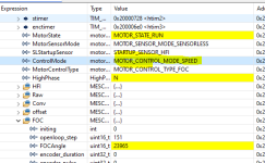
I made some progress in being to spin the motor in speed mode using the Debug feature in CubeIDE. I have set the Control Mode to Speed but somehow I see it back to Torque mode in CubeIDE after starting the debug session..
So anyway, before switching to Speed mode, I set these under FOC. My default speed_kp=0.5 and speed_ki = 0.1.

1743524848379.png

then I switched to Speed mode ( entering 1 opposite ControMode ) and after this, I could spin the motor.
1743524975264.png

by changing speed_req in increasing numbers, I can increase the motor speed. The tricky part is determining speed_kp and speed_ki ( which I haven't figured out what's a good setting). Initially, I get overcurrent errors. I am using a small outrunner motor: 320kv-16s 20A max motor. After some trial and error, I was able to get a sensible value ( I think ) for speed_kp.
 
Last edited:
Hi zpc128,

I thought I'd share what I found since mxlemming is away for a while and may not be able to answer our questions.

I made some progress in being to spin the motor in speed mode using the Debug feature in CubeIDE. I have set the Control Mode to Speed but somehow I see it back to Torque mode in CubeIDE after starting the debug session..
So anyway, before switching to Speed mode, I set these under FOC. My default speed_kp=0.5 and speed_ki = 0.1.

View attachment 368119

then I switched to Speed mode ( entering 1 opposite ControMode ) and after this, I could spin the motor.
View attachment 368120

by changing speed_req in increasing numbers, I can increase the motor speed. The tricky part is determining speed_kp and speed_ki ( which I haven't figured out what's a good setting). Initially, I get overcurrent errors. I am using a small outrunner motor: 320kv-16s 20A max motor. After some trial and error, I was able to get a sensible value ( I think ) for speed_kp.

I figured out how to make it work, and be writable via the terminal. I added the 2 parameters speed_kp and speed_request with the RW attribute . I could have added speed_ki but for now in my setup I did not have to change it. So the 2 lines added are

TERM_addVar(mtr[0].FOC.speed_req , -4096.0f , 4096.0f , "speed_req" , "FOC_speed_request" , VAR_ACCESS_RW , NULL , &TERM_varList);

TERM_addVar(mtr[0].FOC.speed_kp , -4096.0f , 4096.0f , "speed_kp" , "Speed proportional gain Kp" , VAR_ACCESS_RW , NULL , &TERM_varList);


After rebuilding, I change the mode to speed mode, entered the speed_kp that worked for my case and then issued the command by setting speed_req to , say 20. I was successful in being able to control the speed via the terminal.
 
Well done on getting this to work. I have no idea how i got it to work without the variables being in the terminal, can only guess that some commit/merge erased them. I'll add them back. Just got to the end of a very exhausting European tour visiting various factories and colleagues and clients...

Regarding kp and ki... The way to determine them i think is to choose a bandwidth w and then
kp=w/J and
ki=kp*J/f

Where J is the rotational inertia and f is the viscous friction coefficient. w should be between 0 and the speed control loop frequency... 100hz by default... You can't go higher than the control loop frequency.

But in practice, mostly you wouldn't know J or f so tuning with ki=0 and increasing kp until it responds quickly without oscillating and then increasing ki until the steady state error is largely eliminated without oscollation is probably easier in most cases.
 
Well done on getting this to work. I have no idea how i got it to work without the variables being in the terminal, can only guess that some commit/merge erased them. I'll add them back. Just got to the end of a very exhausting European tour visiting various factories and colleagues and clients...

Regarding kp and ki... The way to determine them i think is to choose a bandwidth w and then
kp=w/J and
ki=kp*J/f

Where J is the rotational inertia and f is the viscous friction coefficient. w should be between 0 and the speed control loop frequency... 100hz by default... You can't go higher than the control loop frequency.

But in practice, mostly you wouldn't know J or f so tuning with ki=0 and increasing kp until it responds quickly without oscillating and then increasing ki until the steady state error is largely eliminated without oscollation is probably easier in most cases.
Thank you. I appreciate very much that even with your busy schedule at work/home you are able to provide useful information to guide us in learning about this system.

Overall, I was able to spin the motor using speed control but at lower speeds, I see that sometimes the motor stalls. I am using sensorless mode so I suppose that explains it. The tuning part I will deal later. Maybe an improvement at some point would be to try to estimate the inertia and the friction of the motor within the code to get a better handle on KP and Ki.

Currently, I am looking at using Position control with the goal of being to use the MESC/MP2 as a servo controller. I am using an AS5600 encoder using the I2C interface and some guy has used this before althouhg on a different platform ( ghent360 - Overview). I decided to use the libraries since the AS5600 is cheap and with a few 3-d printed parts can be mounted on a motor.

I did look at the .ioc file that came with the project and noticed that UART3 uses the same pins as the I2C2 interface. on the f405 pill. I disabled UART3, ernabled I2C2 and remove references to |huart3 in main.c ( a few lines below)

UART_HandleTypeDef huart3;
DMA_HandleTypeDef hdma_usart3_tx;
.....

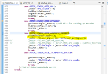
After adding the calls to the libraries for the sensor, a few modifications to the code ( motor sensor mode set to Absolute encoder) , and setting FOC.enc_angle= angle from the AS5600 sensor, I am sort of lost as to what other configuration I need to do.


1744901632845.png

specifically on this part
1744901912397.png

I assume that the pos.set_position is the target position but I am confused why it has to be incremented every time the function is called? Where is FOC.PLL_angle set?

Thanks in advance.
 

Attachments

  • 1744901516134.png
    1744901516134.png
    43.3 KB · Views: 0
  • 1744901719415.png
    1744901719415.png
    20.7 KB · Views: 0
The position controller isn't really useful. The hard part of position control is setpoint generation, i never got around to that.

The pll angle is set after the observer or other angle source is run. Its not intended to be modified by the user.

I think you might find i2c is too slow to be used in a high performance position controller. Better to try SPI or best incremental one.

Thank you. I appreciate very much that even with your busy schedule at work/home you are able to provide useful information to guide us in learning about this system.

Overall, I was able to spin the motor using speed control but at lower speeds, I see that sometimes the motor stalls. I am using sensorless mode so I suppose that explains it. The tuning part I will deal later. Maybe an improvement at some point would be to try to estimate the inertia and the friction of the motor within the code to get a better handle on KP and Ki.

Currently, I am looking at using Position control with the goal of being to use the MESC/MP2 as a servo controller. I am using an AS5600 encoder using the I2C interface and some guy has used this before althouhg on a different platform ( ghent360 - Overview). I decided to use the libraries since the AS5600 is cheap and with a few 3-d printed parts can be mounted on a motor.

I did look at the .ioc file that came with the project and noticed that UART3 uses the same pins as the I2C2 interface. on the f405 pill. I disabled UART3, ernabled I2C2 and remove references to |huart3 in main.c ( a few lines below)

UART_HandleTypeDef huart3;
DMA_HandleTypeDef hdma_usart3_tx;
.....

After adding the calls to the libraries for the sensor, a few modifications to the code ( motor sensor mode set to Absolute encoder) , and setting FOC.enc_angle= angle from the AS5600 sensor, I am sort of lost as to what other configuration I need to do.


View attachment 368862

specifically on this part
View attachment 368864

I assume that the pos.set_position is the target position but I am confused why it has to be incremented every time the function is called? Where is FOC.PLL_angle set?

Thanks in advance.

 
I see that the tle5012 sensor using SPI has been tried in the past. I will try to get hold of this sensor instead of using an I2C sensor later. You are right that I2c maybe a bit slow but for now I just want to understand position control, if I could somehow make it work, even if it is slow.

I think this is the part in MESfoc.c where PLL_angle is set.

Code:
ifdef USE_SPI_ENCODER
      tle5012(_motor);
#endif

//RunPLL for all angle options
    _motor->FOC.PLL_angle = _motor->FOC.PLL_angle + (int16_t)_motor->FOC.PLL_int + (int16_t)_motor->FOC.PLL_error;
//We add the proportional error here since we did not add it last iteration
    _motor->FOC.PLL_error = _motor->FOC.PLL_kp * (int16_t)(_motor->FOC.FOCAngle - (_motor->FOC.PLL_angle & 0xFFFF));
    _motor->FOC.PLL_int = _motor->FOC.PLL_int + _motor->FOC.PLL_ki * _motor->FOC.PLL_error;
    _motor->FOC.eHz = _motor->FOC.PLL_int * _motor->FOC.pwm_frequency*0.00001526f;//1/65536

Would you please explain he above code segment is doing?, I see there are the FOC.PLL_kp and FOC.PLL_ki which are the proportional and integral gains in a PI controller but I don't understand this part

motor->FOC.PLL_angle & 0xFFFF));

Why is it being masked with 0xFFFF?
 
I see that the tle5012 sensor using SPI has been tried in the past. I will try to get hold of this sensor instead of using an I2C sensor later. You are right that I2c maybe a bit slow but for now I just want to understand position control, if I could somehow make it work, even if it is slow.

I think this is the part in MESfoc.c where PLL_angle is set.

Code:
ifdef USE_SPI_ENCODER
      tle5012(_motor);
#endif

//RunPLL for all angle options
    _motor->FOC.PLL_angle = _motor->FOC.PLL_angle + (int16_t)_motor->FOC.PLL_int + (int16_t)_motor->FOC.PLL_error;
//We add the proportional error here since we did not add it last iteration
    _motor->FOC.PLL_error = _motor->FOC.PLL_kp * (int16_t)(_motor->FOC.FOCAngle - (_motor->FOC.PLL_angle & 0xFFFF));
    _motor->FOC.PLL_int = _motor->FOC.PLL_int + _motor->FOC.PLL_ki * _motor->FOC.PLL_error;
    _motor->FOC.eHz = _motor->FOC.PLL_int * _motor->FOC.pwm_frequency*0.00001526f;//1/65536

Would you please explain he above code segment is doing?, I see there are the FOC.PLL_kp and FOC.PLL_ki which are the proportional and integral gains in a PI controller but I don't understand this part

motor->FOC.PLL_angle & 0xFFFF));

Why is it being masked with 0xFFFF?
The pll angle is a uint32t and the foc angle is uint16t. This is so that the pll can track a large number of multi turns for position control (65536 revolutions). When the math to get the difference is run you need to discard the extra 16 bits otherwise the result is nonsense.
 
The pll angle is a uint32t and the foc angle is uint16t. This is so that the pll can track a large number of multi turns for position control (65536 revolutions). When the math to get the difference is run you need to discard the extra 16 bits otherwise the result is nonsense.

Got that part. So the missing bit is to keep track of the number of revolutions between PLL_angle and FOCangle and calculate properly the muliturn angular difference, in radians or degrees. I have other questions if you don't mind.

What is the advantage of calculating PLL_angle based on the previous values of PLL_int and PLL_error? Why not use the current values ? And where is the part referring to the last iteration in "We add the proportional error here since we did not add it last iteration". I looked at the code and could not figure this out.

Thanks again.
 
Interesting project. Has anyone implemented water cooling to one of these controllers? I have a 90v battery that I might expand to 135v that can supply 400a. I doubt I'll ever use the full potential of the pack, but I'd like to know what kind of amperage the mp2 could handle at that 90v or 135v mark.
 
Interesting project. Has anyone implemented water cooling to one of these controllers? I have a 90v battery that I might expand to 135v that can supply 400a. I doubt I'll ever use the full potential of the pack, but I'd like to know what kind of amperage the mp2 could handle at that 90v or 135v mark.
You're very unlikely to get 400A out of this with 150V FETs. Even with 100V ones i don't think it's a good idea...

Don't overdo the busbar. The risk of board warp and damage out does the benefits beyond a few mm2.

Honestly with a400A battery i think you need a bigger controller.
 
The batteries are total overkill for my project, but they were cheap and gives more capacity over the smaller batteries I've been playing with.

I have found another member here that is using the same "motor" I'm using. It was mentioned 200A continuous and 400A burst. I also have liquid cooling setup on this bike and plan to also cool the controller. The plan is not to hammer on this controller. I believe you can set various "power levels" in VESC and set timeouts for it.

Are there any other FETs in the 220 package that might handle more amperage at 150-200v? I'd like to go this path since it's a "serviceable" controller with "easy" to replace fets.

I do believe there's a specific thickness needed for the phase lugs since they key into the pcb? Is the large rectangular shape a heat spreader? I haven't seen any assembled pictures with that bar?
 
The batteries are total overkill for my project, but they were cheap and gives more capacity over the smaller batteries I've been playing with.

I have found another member here that is using the same "motor" I'm using. It was mentioned 200A continuous and 400A burst. I also have liquid cooling setup on this bike and plan to also cool the controller. The plan is not to hammer on this controller. I believe you can set various "power levels" in VESC and set timeouts for it.

Are there any other FETs in the 220 package that might handle more amperage at 150-200v? I'd like to go this path since it's a "serviceable" controller with "easy" to replace fets.

I do believe there's a specific thickness needed for the phase lugs since they key into the pcb? Is the large rectangular shape a heat spreader? I haven't seen any assembled pictures with that bar?
Most people have just soldered wires into the phase lug mounting points.

CRST073N15N,
Ipp051n15
They're probably the best easily available at the moment. Might be some magic ones around.

Usually the 100C rating is a good indicator of the phase current you can use if you cool it really really well.
 
NTP5D0N15MC seems to have a higher rating? Does anyone have an idea of the surface area for watercooling? I found a few premade blocks that are 120mm by 40mm.
 
NTP5D0N15MC seems to have a higher rating? Does anyone have an idea of the surface area for watercooling? I found a few premade blocks that are 120mm by 40mm.
It's similar to the infineon. Both 4.xmohm. the current rating for FETs is fiction. I saw an appnote by TI where they proved the continuous current rating by brazing the drain to a cubic foot of water cooled copper.

Personally, I think infineon is king, all others are bending reality and pushing the limits of QC ability to get better specs. I used to love on semi but recently I've had a lot of issues.
 
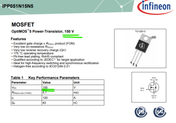
Ipp051n15 is only rated to 100v. What about the IRF150P221AKMA1 instead? I just want to have enough headroom to run 30 or 36s later on.
 
Ipp051n15 is only rated to 100v. What about the IRF150P221AKMA1 instead? I just want to have enough headroom to run 30 or 36s later on.
1753352730981.png

I feel like we are looking at a different IPP051N15, but the N15 refers to the voltage rating so I imagine your version of it is the wrong one...

IRF150P221AKMA1 you suggested is... a totally different package so unlikely to fit.
 
I see what happened now, mouser sent me at that one since the ipp051n15n5 isn't in stock. Looks like there's a long backload for them. I see some listing elsewhere, but I'm all but certain it'll be counterfeits
.
 
Back
Top