• Hello ES! We could use some help to get us past the finish line on building the new knowledgebase for the forum.
    Can you donate? Please see our fundraising page. Thank you!

DIY College EBike

GoFastGus

⚡ Regular
Joined
Mar 31, 2025
Messages
217
Location
Madison, WI
Hi everyone, first post, thought I'd introduce myself

I'm a senior at UW Madison majoring in History & Legal Studies, but I've always been a tinkerer (Legos since a kid, yada yada yada) and someone who very much loves going fast. Madison's a super bikeable city, and after riding my dad's old Schwinn road bike around campus for half a year, I wanted to go faster and figured the quicker way around town would be with an electric bike. After talking with my uncle, who's an avid mountain biker of several decades, he thought that the better bang for my buck (and a good project to boot) would be to buy a hardtail mountain bike and add on an electric bike kit, rather than buy a premade electric bike from a store.

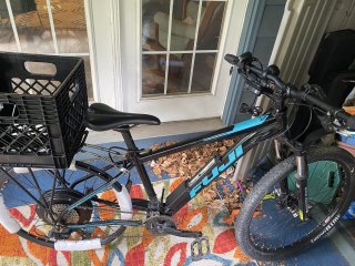
So this spring, I picked up a 2022 Fuji Nevada 27.5 1.5 off of Facebook for $275; it was in pretty good condition with minor wear. According to the original sellers at Dreambikes, It was a pandemic-era bike using whatever components Fuji had laying around, so instead of having Shimano brakes this one has Tektro. Same Microshift Marvo LT 2x9 shifter, though.
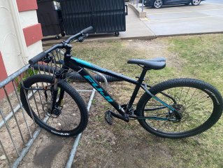
New Bike.jpg

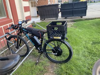
I got it ready for commuting around town, and it quickly became my transportation of choice.
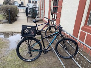
W- the milk crate.JPEG

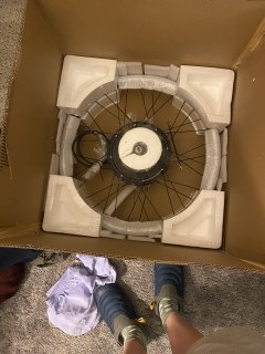
Pretty soon after, I pulled the trigger on my first piece: the Leaf Bike 1500W 27.5x1.95 wheel, hub motor & 7spd cassette assembly
New Motor.JPEG
(Yes I live in squalor, and by my own volition, no less!!)

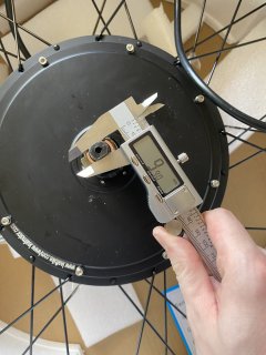
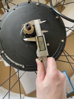
I had gotten by first pair of calipers in anticipation of this project, and I took measurements of everything I could
Axle width.JPEG

Some measurements were more useful than others.
Gotta know that too ig.JPEG

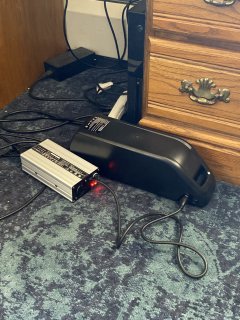
I also got a battery: a Risunmotor 52V 45A 20AH downtube battery. I've now done more research and recognize that this is a remake of the Grin design for a third of the price, but retrospectively even if I knew that I'm not sure I would have spent $500+ more on the name-brand one. I'm hoping that doesn't come back to bite me later.
IMG_1638.JPEG

Once school was out I brought the entire setup home to test out (not pictured: battery).
Test fitting the motor.JPEG
I'm putting off studying for a quiz tomorrow, so P2 will continue later.

Hope y'all like this, and maybe more importantly, can help me build something faster for next time!
 
Curious to see how it goes. What winding of leaf did you order? just the default 4T?

What's the plan for torque arms?
 
Torque arm(s) is a must especially if you plan to use regen.
Define faster- my leaf 1500 will do 40+mph@60V.
 
Take some of the money you think you saved on the battery, and spend it on two Grin torque arms. That’s around $70 on Amazon. Leaf cuts their axles on the short side, but it looks like there’s enough on the cassette side, looking at your pic.

The cells in the Grin pack are name brand Panasonic, rated at 10A continuos, in a 14S6P configuration. Your “Rissun” pack uses a generic cells rated at <9A continuous (surprisingly there’s a cell data sheet), in a14S4P configuration. The cells in the Grin pack can provide 60A continuous and the “Rissun” pack can provide 35A. Even though Grins pack can provide 60A, they conservatively use a 40A BMS. “Rissun” uses a 45A BMS on a pack only capable of 35A. I don’t see where the Rissun pack is remake of Grin, and skeptical of your research.
 
This bike will be able to cruise faster than you'd want to, even if you limit it to only 1800W. It will prove very practical, and you might get a 30 mile range @ 30 mph. You probably don't want to go any faster. If you don't already have one and want to extend your range ~15-20% on the same battery pack, get a torque-sensing bottom bracket.
 
You bought a 52V20AH Risun pack. . The spec states "5000mAH 3C Powerful DMEGC INR21700 Cell". The 3C indicates it has a 15A discharge current, which gives you a battery capable of 60A, but that's limited by the 45A BMS. A comparable Grin 52V20AH battery uses Samsung 18650 GA cells. The cell specs say the battery is capable of 60A, but it has a 40A BMS which limits safe operation. I think both of these are similar as far as performance and will run your DD motor,

I've used GA cells in my batteries and think they're great. However, Google says that DMEGC is well respected battery supplier in the solar area. The RisunMotor still seems cheap, but maybe it will be OK for longevity and safety.

Hope it works out. Meanwhile, follow the battery safety proocol. Never charge unsupervised. Don't recharge when battery internal temperature is below 40-45F.
 
Take some of the money you think you saved on the battery, and spend it on two Grin torque arms. That’s around $70 on Amazon. Leaf cuts their axles on the short side, but it looks like there’s enough on the cassette side, looking at your pic.

The cells in the Grin pack are name brand Panasonic, rated at 10A continuos, in a 14S6P configuration. Your “Rissun” pack uses a generic cells rated at <9A continuous (surprisingly there’s a cell data sheet), in a14S4P configuration. The cells in the Grin pack can provide 60A continuous and the “Rissun” pack can provide 35A. Even though Grins pack can provide 60A, they conservatively use a 40A BMS. “Rissun” uses a 45A BMS on a pack only capable of 35A. I don’t see where the Rissun pack is remake of Grin, and skeptical of your research.
Thanks for the info! I'll be the first to admit I'm very much at the beginning of the learning curve here, so I appreciate all the skepticism and knowledge from people who know more than me.
 
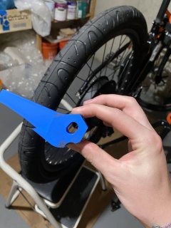
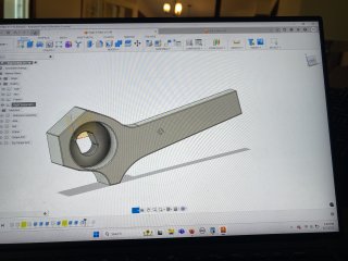
P2: Made some torque arms for the bike. I started by designing in Autodesk Fusion 360, then 3d printing them at a local makerspace out of PLA plastic to test fit them.
A more final design (can you tell I flunked out of engineering).JPEG
This is a more final design, but you can see where I've marked fitment issues with the derailleur and frame. This was my first time using CAD for a project where I actually had some creative freedom, so it was a real learning curve (it still is).

I also bought tires, Maxxis Hookworm 27.5 x2.5 slicks. Madison gets lots of ice and salt on the roads in the winter, so over Thanksgiving or winter break I'll order some Schwalbe studded tires and swap them over.

With lots of help from the makerspace's resident engineer, I finalized my design in CAD.
Some more info on the design:
Left & right have different designs (accomodating derailleur on right, extra bracket on left).
Both are 30.75mm wide, 15.75mm wide section of metal locates the axle up/down & front/back, connecting to a 70mm long 15mm wide stem that is anchored to the frame via hose clamps. At the time of this writing, I am considering upgrading to U bolts and/or utilizing the bracket on the left side of the frame to better anchor the torque arms.
Final Torque Arm design.JPEG

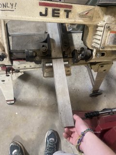
I made the torque arms out of some aluminum stock lying around. No clue what alloy, if someone else knows I'd love to find out just to have that knowledge.
Cutting stock to size.JPEG

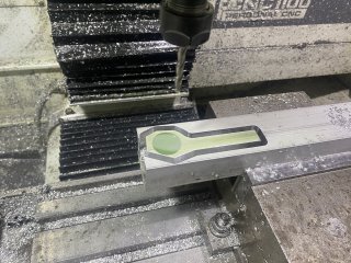
This was my first time ever using a CNC mill, so the engineer there had to design my tool paths and work the mill for me. I know I have my whole life ahead of me to learn how to use all these tools but I really can't wait to get better.
CNC-milling.JPEG

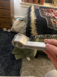
Here's the finished product; it was necessary to hand mill back side of the stem off because it would have interfered with the frame, and flipping the part over to CNC mill it would probably have been a waste of time. Obviously, some hand filing was needed to finish it all up.
Filing still needed.JPEG

This is what the bike looked like with torque arms installed. Note the lack of a rear brake (only running regen back there) and at this point the lack of a front caliper. I spent some time figuring out the right ebrake lever for my bike's controller and mineral oil brakes, only to discover that I would have to make my own. For the first week or so of this bike running, I ran it at the lowest setting (under 15mph) and could only stop via regen or shoes to the asphalt. Suffice it to say, wouldn't recommend.
Running & driving bike.JPEG

With the bike effectively running and driving, I could now turn to all the little things (like physical brakes) that make a bike actually daily driveable.
 
Last edited:
This bike will be able to cruise faster than you'd want to, even if you limit it to only 1800W. It will prove very practical, and you might get a 30 mile range @ 30 mph. You probably don't want to go any faster. If you don't already have one and want to extend your range ~15-20% on the same battery pack, get a torque-sensing bottom bracket.
Impressive! Yeah above 35mph, this thing starts to get a little sketchy. It'll get me 25-30 miles range at residential traffic speeds.

That torque sensing bottom bracket sounds like a great idea! I'll have to do some research into that. Currently, I'm in the middle of reattaching my shifting system so my pedals spin but don't move anything at the moment (I'll post about it when I'm done with the whole tangent). Would a torque-sensing bottom bracket still be helpful in that case?
 
Curious to see how it goes. What winding of leaf did you order? just the default 4T?

What's the plan for torque arms?
3T, website says top speed of 45mph. On a good flat road with no winds, they're pretty dead on.

RE: torque arms, I posted a lot about them in P2, but here are some additional details: I use zinc-plated 21mm nuts to anchor the torque arms to the axles and frame. I use 4 stainless steel hoseclamps at the time of this writing to anchor the stem of the torque arm to the frame.
 
Last edited:
Aluminum not recommended for TAs-- it's too soft. Ideally you want material properties close to that of the axle itself. So it will not cut into the axle, and the axle will not cut into it. Steel is a good choice and commonly available, nothing fancy.

Also important is that it should fit the axle snugly. Otherwise known as interference fit. Best to slightly undersize the hole and carefully file it out until it can be installed and replaced by only tapping it with a small hammer. If there is any slop or rocking, it will only get worse over time, leading to eventual failure.
 
Aluminum not recommended for TAs-- it's too soft. Ideally you want material properties close to that of the axle itself. So it will not cut into the axle, and the axle will not cut into it. Steel is a good choice and commonly available, nothing fancy.

Also important is that it should fit the axle snugly. Otherwise known as interference fit. Best to slightly undersize the hole and carefully file it out until it can be installed and replaced by only tapping it with a small hammer. If there is any slop or rocking, it will only get worse over time, leading to eventual failure.
Thanks for the advice! I originally chose aluminum because I knew it would give out before steel, which would hopefully prevent me breaking my axle instead of my torque arm. As a bonus, it was easier to machine, and I had the correct size of aluminum there.

How do I tell what class of hole fit I have? My 3d printed models slid over the axle without any interference or filing necessary. The tool paths on the CNC mill cut out this shape, and the unfiled part wouldn't fit over the axle. I hand filed it out until it would fit freely over the axle, but I think I slightly overdid it and there's a little bit of slop in it.

Funny you should mention eventual failure, because they've started flexing a whole bunch. I doubled my hose clamps from the original 2 to 4 and they still flex under high load at low speeds. I pulled the trigger on a set of 6mm thick 304 stainless steel torque arms that'll go under my bike frame, which will hopefully be a better fit. I'm gonna try to make these aluminum ones work in the meantime, but depending how these stainless steel ones work out, I might just make torque arms out of mild steel plating like you suggested.
 
I use zinc-plated 21mm nuts to anchor the torque arms to the axles and frame. I use 4 stainless steel hoseclamps at the time of this writing to anchor the stem of the torque arm to the frame.

Somethings to throw into the mix. I do not know what metal that frame is made from.

Zinc is close to alumin(i)um (ex-USA spelling) on the galvanic series, so is generally compatible. Stainless steel will eat aluminium it is in contact with - as in powdery, crumbly aluminium metal. I would rather replace fasteners than frames - particularly with threaded mounting holes in the frame (perhaps not immediately relevant here). This opinion comes from my time working with a professional frame builder with many years of experience.

Do they use salt on the roads there in winter?

Also, regarding your torque arm. Bravo! The experience will carry through to other projects. But...

Consider the Grin v7 torque arm design. They put a clamp on it (and made it more expensive) for a reason. As noted by others, that hard steel flatted axle will prevail over that soft aluminium torque arm and eat it. Even hardened aluminium (various alloys and subsequent heat treatments) won't stand up to that axle. The relative material strengths and the leverage involved given the fixed size of that axle mean that this application is probably not viable.

Put some numbers to the leverage inherent in the dimensions of the axle v. torque arm, add some estimates of the motor torque input, and compare that to the surface hardness of the aluminium - this is a useful exercise. There is no shame in learning from what others have done to make up for their mistakes (Grin in this case). They are not making their solution less attractive (by being more expensive) without a need.

Given the surrounding characteristics (human size and weight, strength of steel bicycle frames, etc.) 250W bicycle motors can often provide useful service without damage - but even then do sometimes. More than 250W in the same environment or with aluminium frames or other variants will fail and cause damage. Flatted axles are not an engineering solution, they are a cheapest-quick-time-to-market solution that was just barely acceptable at first.

Clamp the hollow side of the axle (with the cable passing through) if you wish, but definitely clamp the solid side. Grin writes about this in their pages about the torque arm design. The hollow side is much weaker.
 
Last edited:
Would a torque-sensing bottom bracket still be helpful in that case?
If you can configure your computer to use it as a cadence sensor instead and set it up appropriately, yes. Then you can set it up for torque-sensing after you have the pedal drivetrain functional.

My Cycle Analyst v3 allows for this.
 
Last edited:
3T, website says top speed of 45mph. On a good flat road with no winds, they're pretty dead on.

RE: torque arms, I posted a lot about them in P2, but here are some additional details: I use zinc-plated 21mm nuts to anchor the torque arms to the axles and frame. I use 4 stainless steel hoseclamps at the time of this writing to anchor the stem of the torque arm to the frame.
You're eventually going to want to move that 3T over to something built to go much faster, I presume? With your rear wheel size and an upgrade to a 72V pack, in an aerodynamically slippery enough vehicle, you could be looking at close to 90 mph top speed.

Any cruising speed over 35 mph on an upright bicycle, and I would go with nothing less than full suspension and DOT3/4 compatible hydraulic disc brakes with a motorcycle fluid reservoir. Want to go over 40 mph, and you'll want DOT rims/tires as well. Also, over 40 mph, you'll probably want a longer wheelbase for stability.
 
Last edited:
3T, website says top speed of 45mph. On a good flat road with no winds, they're pretty dead on.

hmm.. unless you are respoking that into a much smaller wheel then you will need a much stronger battery ( 60-80A output ) to power this super low voltage, high amperage winding.

It sounds like your BMS is conservative relative to the power output of your cells so you might want to consider a BMS bypass for discharge. Otherwise it's likely you can't attain the top speed and it will bog down on hills a lot due to insufficient amps.

For 45mph i would use really strong regenerative braking because bicycle brakes start to fail to work around that speed.. and full suspension or super fat tires is mandatory at this point too. But.. your battery pack is probably not capable of that.
 
Last edited:
Somethings to throw into the mix. I do not know what metal that frame is made from.

Zinc is close to alumin(i)um (ex-USA spelling) on the galvanic series, so is generally compatible. Stainless steel will eat aluminium it is in contact with - as in powdery, crumbly aluminium metal. I would rather replace fasteners than frames - particularly with threaded mounting holes in the frame (perhaps not immediately relevant here). This opinion comes from my time working with a professional frame builder with many years of experience.
It's an aluminum frame, Fuji says it's an A2-SL front triangle and Al-SL rear triangle. Are those just their proprietary names for the alloys? The nuts are zinc-plated steel; it rusts when exposed to enough water so I'm guessing some sort of mild steel.
Do they use salt on the roads there in winter?
In enough places around town that it's a concern.

Also, regarding your torque arm. Bravo! The experience will carry through to other projects. But...

Consider the Grin v7 torque arm design. They put a clamp on it (and made it more expensive) for a reason. As noted by others, that hard steel flatted axle will prevail over that soft aluminium torque arm and eat it. Even hardened aluminium (various alloys and subsequent heat treatments) won't stand up to that axle. The relative material strengths and the leverage involved given the fixed size of that axle mean that this application is probably not viable.
The Grin V7 is also made of stainless steel though. Should I put zinc-plated mild steel washers in between the torque arms and the frame then, or something else? Or is a stainless steel axle not a viable choice for me?
Put some numbers to the leverage inherent in the dimensions of the axle v. torque arm, add some estimates of the motor torque input, and compare that to the surface hardness of the aluminium - this is a useful exercise. There is no shame in learning from what others have done to make up for their mistakes (Grin in this case). They are not making their solution less attractive (by being more expensive) without a need.
I'm not quite clear on the experimental setup to make this happen. What are you envisioning?
Given the surrounding characteristics (human size and weight, strength of steel bicycle frames, etc.) 250W bicycle motors can often provide useful service without damage - but even then do sometimes. More than 250W in the same environment or with aluminium frames or other variants will fail and cause damage. Flatted axles are not an engineering solution, they are a cheapest-quick-time-to-market solution that was just barely acceptable at first.

Clamp the hollow side of the axle (with the cable passing through) if you wish, but definitely clamp the solid side. Grin writes about this in their pages about the torque arm design. The hollow side is much weaker.
 
If you can configure your computer to use it as a cadence sensor instead and set it up appropriately, yes. Then you can set it up for torque-sensing after you have the pedal drivetrain functional.

My Cycle Analyst v3 allows for this.
I have a Risunmotor 48V 45A controller with a UKC-1 display. I have a PAS input, but I'll have to do some more reading about if the controller has a way to use it as a cadence sensor.
 
You're eventually going to want to move that 3T over to something built to go much faster, I presume? With your rear wheel size and an upgrade to a 72V pack, in an aerodynamically slippery enough vehicle, you could be looking at close to 90 mph top speed.

Any cruising speed over 35 mph on an upright bicycle, and I would go with nothing less than full suspension and DOT3/4 compatible hydraulic disc brakes with a motorcycle fluid reservoir. Want to go over 40 mph, and you'll want DOT rims/tires as well. Also, over 40 mph, you'll probably want a longer wheelbase for stability.
The money to replace the frame, hubmotor, brake system and battery is a little way off, but my research should start sooner rather than later. A few follow up questions:
  1. What brands would you recommend looking at for used full suspension bikes that can fit wider DOT wheels and tires?
  2. I haven't yet seen a bike brake system with a motorcycle reservoir. Would that be custom made with some really nice brake calipers, huge rotors, and a motocycle lever and reservoir? Are there any threads you could link to about that?
  3. For DOT wheels, where should I look for rims and spokes?
My understanding of how winding, wheel size, voltage, and amperage all interact is poor at best, are there any threads or resources you'd recommend checking out?
 
hmm.. unless you are respoking that into a much smaller wheel then you will need a much stronger battery ( 60-80A output ) to power this super low voltage, high amperage winding.
It sounds like your BMS is conservative relative to the power output of your cells so you might want to consider a BMS bypass for discharge. Otherwise it's likely you can't attain the top speed and it will bog down on hills a lot due to insufficient amps.
Bypassing BMSs is entirely new to me, I'm building some sort of switch to skip the BMS, and maybe some sort of fuse or something to protect against overdraw?
For 45mph i would use really strong regenerative braking because bicycle brakes start to fail to work around that speed.. and full suspension or super fat tires is mandatory at this point too. But.. your battery pack is probably not capable of that.
Risun warns that at the third level of regen braking the force can damage a frame. I have the regen on the base setting right now, it's worth looking to see what setting it's on by default. Hopefully I still have room to grow without breaking anything.
 
Controllers protect against overdraw by their nature. A switch would eventually wear out from sparks, and you'd need it ON most of the time since the amps you can output @ 45A are never adequate for a 3T.

It would be fine to use the clamping torque arms on whatever frame you like.
You may have some corrosion over time but the answer to that is to tighten the clamp after cleaning it :)
 
Risun warns that at the third level of regen braking the force can damage a frame. I have the regen on the base setting right now, it's worth looking to see what setting it's on by default. Hopefully I still have room to grow without breaking anything.

That's assuming you aren't using a pair of clamping torque arms. Regen should never be used with out torque arms in the first place - that will destroy a dropout in short order with a powerful motor.
 
Back
Top