• Hello ES! We could use some help to get us past the finish line on building the new knowledgebase for the forum.
    Can you donate? Please see our fundraising page. Thank you!

Modular, Multi-Platform, 300A ESC

Also, I completely understand this would require a board redesign, but what about a IXFK300N20X3 in a TO-264K package. The board would have to grow a good bit in size. But we'd be able to fit larger electrolytics on the edge and we'd have parts with a 200v rating that would be very safe for a 36s setup. Yes, it's about double in size, but that doubling also affords much more current capacity past double the current mosfets. If you guys are pushing the 120A rated mosfets to 300a, I wonder what a 300a rated mosfet could do.
 
Hey guys,


I put together a FOC-KING ESC(link) but ran into some issues with the ADC inputs(video). I compared the schematics with the MP2-ESC and saw that the MP2 uses pull-down resistors, caps, and series resistors on the ADC lines.


I tried adding a 0.1 µF cap and a 6.8 kΩ pull-down resistor to the ADC, and now it’s working perfectly. IMG_20250802_171023.jpg

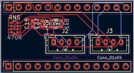
Now I’m thinking about making a small PCB that sits on top of my “PILL” and adds connectors for ADC and UART.
Snímka obrazovky 2025-08-03 222515.png

Do you think I can use this circuit from MP2-ESC for my PILL?
Snímka obrazovky 2025-08-02 132045.png


Thanks!
 
I got myself a 1000w hub motor powered by a 40V,20AH battery which I am using with MESC and MP2 to build an ebike. Right now, using torque control i am able to spin the motor on the bench. Some settings I am using.

#define DEFAULT_SENSOR_MODE MOTOR_SENSOR_MODE_SENSORLESS
#define DEFAULT_CONTROL_MODE MOTOR_CONTROL_MODE_TORQUE
#define DEFAULT_SENSOR_MODE MOTOR_SENSOR_MODE_OPENLOOP

When it spins, the speed seems smooth as I increase the throttle. However, it doesn't start up well all the time. The motor has Hall sensors but I haven't hooked it up yet to the controller since I still have to figure out how to wire it. I got the motor from someone else and it did not come with information on which pins/wires are Hall A/B/C.

Anyway, | see there's an option for HFI injection. for startup. I gave it a try by using these settings

#define DEFAULT_STARTUP_SENSOR STARTUP_SENSOR_HFI
#define HFI_VOLTAGE 1.0f
#define HFI_TEST_CURRENT 0.0f
#define HFI_THRESHOLD 0.0f //Defaults to 0.05Vbus if set to 0
#define DEFAULT_HFI_TYPE HFI_TYPE_45

but still would not start well at all times. Is HFI suitable for my motor? What other things should I be setting?

I can give the bike a little push forward so that startup won't be an issue but it would feel good to make it work all the way from standstill to full speed.

Help is greatly appreciated.
 
Hi

Good work getting it running!

You need to connect over USB and set it up. The default parameters are really just there for if you want to set up a batch of things, not for experimenting. I've gradually added them as defaults as and when various specific use cases have arisen.

Regarding the hall sensors, mesc is indifferent to the connection order. You should use sensorless mode with hall startup... The SL_sensor in the terminal. You have to get it to spin up once under sensorless with the use hall start parameter set and it then populates a table making the sensorless to the hall states, and then should work.

The HFI has to have the minimum speed set in the terminal as well as the voltages.

For a hub motor you probably need 3 or 4 volts of HFI voltage. Many hub motors won't work atall with HFI, there's no salience in them.
I got myself a 1000w hub motor powered by a 40V,20AH battery which I am using with MESC and MP2 to build an ebike. Right now, using torque control i am able to spin the motor on the bench. Some settings I am using.

#define DEFAULT_SENSOR_MODE MOTOR_SENSOR_MODE_SENSORLESS
#define DEFAULT_CONTROL_MODE MOTOR_CONTROL_MODE_TORQUE
#define DEFAULT_SENSOR_MODE MOTOR_SENSOR_MODE_OPENLOOP

When it spins, the speed seems smooth as I increase the throttle. However, it doesn't start up well all the time. The motor has Hall sensors but I haven't hooked it up yet to the controller since I still have to figure out how to wire it. I got the motor from someone else and it did not come with information on which pins/wires are Hall A/B/C.

Anyway, | see there's an option for HFI injection. for startup. I gave it a try by using these settings

#define DEFAULT_STARTUP_SENSOR STARTUP_SENSOR_HFI
#define HFI_VOLTAGE 1.0f
#define HFI_TEST_CURRENT 0.0f
#define HFI_THRESHOLD 0.0f //Defaults to 0.05Vbus if set to 0
#define DEFAULT_HFI_TYPE HFI_TYPE_45

but still would not start well at all times. Is HFI suitable for my motor? What other things should I be setting?

I can give the bike a little push forward so that startup won't be an issue but it would feel good to make it work all the way from standstill to full speed.

Help is greatly appreciated.
 
Hi

Good work getting it running!

You need to connect over USB and set it up. The default parameters are really just there for if you want to set up a batch of things, not for experimenting. I've gradually added them as defaults as and when various specific use cases have arisen.

Regarding the hall sensors, mesc is indifferent to the connection order. You should use sensorless mode with hall startup... The SL_sensor in the terminal. You have to get it to spin up once under sensorless with the use hall start parameter set and it then populates a table making the sensorless to the hall states, and then should work.

The HFI has to have the minimum speed set in the terminal as well as the voltages.

For a hub motor you probably need 3 or 4 volts of HFI voltage. Many hub motors won't work atall with HFI, there's no salience in them.
Hi mxlemming,

Thank you very much for the advice. It makes working with MESC and MP2 so much fun for me! I

Anyway, After connecting the hall sensors on the controller and setting opt_hall_start to true using the terminal, I was able to spin the motor much more consistently from start . I did not expect it to be so easy to do.

Now, I want to understand why MESC is indifferent to the Hall sensor wiring . So once the Hall table is populated, I suppose there is information that it can use to determine how the 3 phases will be turned On/Off. If you decide to use the HALL sensors not just for startup, will this Hall table still work, assuming that the wiring is incorrect?

Another question I have is about settings and where they are saved:

In the past, I wanted to change the limits of the throttle from 1200--> 4095 to the values show below:

In my code in, I have set the following

#define ADC1MIN 800
#define ADC1MAX 1700
#define ADC2MIN 800
#define ADC2MAX 4095

but when I debug using the IDE, i see in input_vars that adc1_MIN is 1200 and adc1_MAX=4095. I searched the code for where this could be changed , but could not find it. Maybe I missed it. Anyway, yesterday I saw there is an option for adc1_min and adc1_max to be set using the terminal. After making the change and saving it, I see now that it updated to the value I set in the terminal. Could you please explain why this is so? So the general rule is to use the terminal to do customization of settings for diffferent motors, like setting pole pairs, inductance, resistance etc?

And one last question:

Now that I could spin the motor consistently from standstill, I experimented with grabbing the wheel to to simulate a bigger load, While I was doing this, I had status start open in the terminal to see the current. I did not see much current, to the order of about 5A briefly but me grabbing the wheel caused the motor to stall, although ESC status in the terminal remains in RUN. I understand that the current is probably higher at the beginning and without a scope won't be able to see the real high value . I am using an assembled battery pack 26650 a123 batteries that are rated for 2.5Ah per cell and 70A continuous discharge, 12 S configuration so I would think there's plenty of juice in it to be able to handle big current demand.

My settings are
1759525351240.png

what am |I missing?

Again many thanks for the help.
 

Attachments

  • 1759524783963.png
    1759524783963.png
    23 KB · Views: 1
Hi mxlemming,

Thank you very much for the advice. It makes working with MESC and MP2 so much fun for me! I

Anyway, After connecting the hall sensors on the controller and setting opt_hall_start to true using the terminal, I was able to spin the motor much more consistently from start . I did not expect it to be so easy to do.

Now, I want to understand why MESC is indifferent to the Hall sensor wiring . So once the Hall table is populated, I suppose there is information that it can use to determine how the 3 phases will be turned On/Off. If you decide to use the HALL sensors not just for startup, will this Hall table still work, assuming that the wiring is incorrect?

Another question I have is about settings and where they are saved:

In the past, I wanted to change the limits of the throttle from 1200--> 4095 to the values show below:

In my code in, I have set the following

#define ADC1MIN 800
#define ADC1MAX 1700
#define ADC2MIN 800
#define ADC2MAX 4095

but when I debug using the IDE, i see in input_vars that adc1_MIN is 1200 and adc1_MAX=4095. I searched the code for where this could be changed , but could not find it. Maybe I missed it. Anyway, yesterday I saw there is an option for adc1_min and adc1_max to be set using the terminal. After making the change and saving it, I see now that it updated to the value I set in the terminal. Could you please explain why this is so? So the general rule is to use the terminal to do customization of settings for diffferent motors, like setting pole pairs, inductance, resistance etc?

And one last question:

Now that I could spin the motor consistently from standstill, I experimented with grabbing the wheel to to simulate a bigger load, While I was doing this, I had status start open in the terminal to see the current. I did not see much current, to the order of about 5A briefly but me grabbing the wheel caused the motor to stall, although ESC status in the terminal remains in RUN. I understand that the current is probably higher at the beginning and without a scope won't be able to see the real high value . I am using an assembled battery pack 26650 a123 batteries that are rated for 2.5Ah per cell and 70A continuous discharge, 12 S configuration so I would think there's plenty of juice in it to be able to handle big current demand.

My settings are
View attachment 378499

what am |I missing?

Again many thanks for the help.
Probably all the things you want are in the terminal. Once you've run save in the terminal once the defaults are ignored. The defaults are there so that if you want to make say 1000 units you don't have to go through a terminal setup procedure.

There are parameters for max power, max battery current and so on... If you type get par it'll give you the relevant list.

One gotcha is that the cube ide only reprograms the program section not the saved data section, so after programming with stlink it will still retain the old saved terminal values unless you erase the entire flash using the st cube programmer or similar. Terminal has an erase command save -d but it can be a bit unreliable for reasons i haven't yet debugged.
 
Last edited:
Probably all the things you want are in the terminal. Once you've run save in the terminal once the defaults are ignored. The defaults are there so that if you want to make say 1000 units you don't have to go through a terminal setup procedure.

There are parameters for max power, max battery current and so on... If you type get par it'll give you the relevant list.

One gotcha is that the cube ide only reprograms the program section not the saved data section, so after programming with stlink it will still retain the old saved terminal values unless you erase the entire flash using the st cube programmer or similar. Terminal has an erase command save -d but it can be a bit unreliable for reasons i haven't yet debugged.
I looked at the parameters in the terminal and I still could not figure out why the torque at startup is not what I expected with such a big hub motor and big battery pack. I am still able to prevent the wheel from spinning by just grabbing it. Here are my settings after some adjustments.

@MESC>get
Parameter | Value | Min | Max | Description
adc1 | 715 | 0 | 4096 | Raw ADC throttle
adc1_max | 1700 | 0 | 4096 | ADC1 max val
adc1_min | 800 | 0 | 4096 | ADC1 min val
adc1_pol | 1.000000 | -1.00 | 1.00 | ADC1 polarity
adc2_max | 4095 | 0 | 4096 | ADC2 max val
adc2_min | 800 | 0 | 4096 | ADC2 min val
adc2_pol | 1.000000 | -1.00 | 1.00 | ADC2 polarity
can_adc | 0 | 0 | 254 | CAN ADC ID 0=disabled
ehz | -0.177025 | -inf | inf | Motor electrical hz
error | 0 | 0 | 429496729| System errors now
error_all | 0 | 0 | 429496729| All errors encountered
FOC_Advance | 0.000000 | -10.00 | 10.00 | FOC advance, proportion of 1 PWM cycle
FOC_angle | 8189 | 0 | 65535 | FOC angle now
FOC_curr_BW | 10000.000000 | 200.00 | 10000.00 | Current Controller Bandwidth
FOC_enc_ang | 25000 | 0 | 65535 | Encoder angle now
FOC_enc_oset | 25000 | 0 | 65535 | Encoder alignment angle
FOC_enc_pol | 0 | 0 | 1 | Encoder polarity
FOC_enc_PPR | 4096 | 0 | 65535 | Encoder ABI PPR
FOC_flux_gain | 1.272792 | 0.00 | 100.00 | Flux linkage gain
FOC_flux_nlin | 5000.000000 | 0.00 | 10000.00 | Flux centering gain
FOC_fpwm | 20000.000000 | 0.00 | 100000.00| PWM frequency
FOC_fw_ehz | 0.000000 | 0.00 | 6000.00 | max eHz under field weakenning
FOC_hall_array_ok | 1 | 0 | 1 | Hall array OK flag (set to 0 to restart live hall cal process)
FOC_hall_iir | 0.950000 | 0.00 | 1.00 | Decay constant for hall preload (0-1.0)
FOC_hall_Vt | 2.000000 | 0.00 | 100.00 | Hall transition voltage
FOC_hfi_eHz | 0.000000 | 0.00 | 2000.00 | HFI Max Frequency
FOC_hfi_type | 0 | 0 | 3 | HFI type [0=None, 1=45deg, 2=d axis]
FOC_hfi_volt | 1.000000 | 0.00 | 50.00 | HFI voltage
FOC_Max_Mod | 0.950000 | 0.10 | 1.12 | Max modulation index; typically 0.95, can over modulate to 1.12
FOC_obs_type | 1 | 0 | 4 | Observer type, 0=None, 1=MXLLambda, 2MXL, 3=OrtegaOrig, 4=PLL
FOC_ol_step | 0 | 0 | 6000 | Angle per PWM period openloop (65535 per erev)
FOC_ortega_gain | 1000000.000000 | 1.00 | 100000000| Ortega gain, typically 1M
Hall_flux | Array[12] | -10.00 | 10.00 | hall start table
id | -0.014807 | -inf | inf | Phase Idq_d smoothed
input_opt | 25 | 0 | 128 | Inputs [1=ADC1 2=ADC2 4=PPM 8=UART 16=Killswitch 32=CANADC1 64=CANADC2 128=ADC12DIFF]
iq | -0.010642 | -inf | inf | Phase Idq_q smoothed
iqreq | 0.000000 | -4096.00 | 4096.00 | mtr[0].FOC.Idq_req.q
meas_cl_curr | 8.500000 | 0.50 | 100.00 | Measuring q closed loop current
meas_curr | 20.000000 | 0.50 | 100.00 | Measuring current
meas_volt | 4.000000 | 0.50 | 100.00 | Measuring voltage
node_id | 0 | 1 | 254 | Node ID
opt_app_type | 0 | 0 | 3 | App type, 0=none, 1=Vehicle, 2,3 = undefined
opt_circ_lim | 2 | 0 | 2 | Circle limiter [0=OFF, 1=ON, 2=ON Vd]
opt_cont_type | 0 | 0 | 4 | Cont type: 0=Torque, 1=Speed, 2=Duty, 3=Position, 4=Measuring, 5=Handbrake
opt_fw | 2 | 0 | 2 | Field weakening [0=OFF, 1=ON, 2=ON V2]
opt_hall_start | true | false | true | Use hall start
opt_lr_obs | false | false | true | Use LR observer
opt_motor_temp | false | false | true | Motor has temperature sensor
opt_mtpa | 0 | 0 | 3 | MTPA type = 0=none, 1=setpoint, 2=magnitude, 3=iq
opt_phase_bal | false | false | true | Use highhopes phase balancing
opt_pwm_type | 0 | 0 | 3 | Modulator [0=SVPWM, 1=sinusoidal, 2=Bottom clamp, 3=Sin/bottom combo]
par_dir | 1 | 0 | 1 | Motor direction
par_flux | 0.016200 | 0.00 | 100.00 | Flux linkage
par_fw_curr | 0.000000 | 0.00 | 300.00 | Max field weakenning current
par_i_max | 90.000000 | 0.00 | 1000.00 | Max motor current
par_i_min | -10.000000 | -1000.00 | 0.00 | Min motor current
par_i_park | 0.000000 | 0.00 | 300.00 | Max current for handbrake
par_ibat_max | 800.000000 | 0.00 | 1000.00 | Max battery current power
par_ld | 0.000025 | 0.00 | 10.00 | Phase inductance
par_lq | 0.000025 | 0.00 | 10.00 | Phase inductance
par_motor_sensor | 0 | 0 | 30 | 0=SL, 1=Hall, 2=OL, 3=ABSENC, 4=INC_ENC, 5=HFI
par_p_max | 12000.000000 | 0.00 | 50000.00 | Max power
par_pp | 16 | 0 | 255 | Motor pole pairs
par_r | 0.172000 | 0.00 | 10.00 | Phase resistance
par_rpm_max | 100 | 0 | 300000 | Max RPM
par_SL_sensor | 0 | 0 | 30 | 0=OL, 1=Hall, 2=PWMENC, 3=HFI
password | | Password for SU
safe_count | 100 | 0 | 1000 | Live count before allowing throttle
safe_start | 100 | 0 | 1000 | Countdown before allowing throttle
speed_ki | 0.100000 | 0.00 | 6000000.0| amps/Hz integral gain
speed_kp | 0.500000 | 0.00 | 6000000.0| amps/Hz proportional gain
speed_req | 0.000000 | 0.00 | 5000.00 | Hz
TMOS | 227.990799 | 0.00 | 4096.00 | MOSFET temp, kelvin
TMOT | 179.206314 | 0.00 | 4096.00 | Motor temp, kelvin
uart_dreq | 0.000000 | -1000.00 | 1000.00 | Uart input
uart_req | 0.000000 | -1000.00 | 1000.00 | Uart input
vbus | 39.845676 | 0.00 | inf | Read input voltage
Vd | 0.112388 | -4096.00 | 4096.00 | FOC_Vdq_d
Vq | -0.105363 | -4096.00 | 4096.00 | FOC_Vdq_q

Anything that could be wrong in my setup?
 
I looked at the parameters in the terminal and I still could not figure out why the torque at startup is not what I expected with such a big hub motor and big battery pack. I am still able to prevent the wheel from spinning by just grabbing it. Here are my settings after some adjustments.

@MESC>get
Parameter | Value | Min | Max | Description
adc1 | 715 | 0 | 4096 | Raw ADC throttle
adc1_max | 1700 | 0 | 4096 | ADC1 max val
adc1_min | 800 | 0 | 4096 | ADC1 min val
adc1_pol | 1.000000 | -1.00 | 1.00 | ADC1 polarity
adc2_max | 4095 | 0 | 4096 | ADC2 max val
adc2_min | 800 | 0 | 4096 | ADC2 min val
adc2_pol | 1.000000 | -1.00 | 1.00 | ADC2 polarity
can_adc | 0 | 0 | 254 | CAN ADC ID 0=disabled
ehz | -0.177025 | -inf | inf | Motor electrical hz
error | 0 | 0 | 429496729| System errors now
error_all | 0 | 0 | 429496729| All errors encountered
FOC_Advance | 0.000000 | -10.00 | 10.00 | FOC advance, proportion of 1 PWM cycle
FOC_angle | 8189 | 0 | 65535 | FOC angle now
FOC_curr_BW | 10000.000000 | 200.00 | 10000.00 | Current Controller Bandwidth
FOC_enc_ang | 25000 | 0 | 65535 | Encoder angle now
FOC_enc_oset | 25000 | 0 | 65535 | Encoder alignment angle
FOC_enc_pol | 0 | 0 | 1 | Encoder polarity
FOC_enc_PPR | 4096 | 0 | 65535 | Encoder ABI PPR
FOC_flux_gain | 1.272792 | 0.00 | 100.00 | Flux linkage gain
FOC_flux_nlin | 5000.000000 | 0.00 | 10000.00 | Flux centering gain
FOC_fpwm | 20000.000000 | 0.00 | 100000.00| PWM frequency
FOC_fw_ehz | 0.000000 | 0.00 | 6000.00 | max eHz under field weakenning
FOC_hall_array_ok | 1 | 0 | 1 | Hall array OK flag (set to 0 to restart live hall cal process)
FOC_hall_iir | 0.950000 | 0.00 | 1.00 | Decay constant for hall preload (0-1.0)
FOC_hall_Vt | 2.000000 | 0.00 | 100.00 | Hall transition voltage
FOC_hfi_eHz | 0.000000 | 0.00 | 2000.00 | HFI Max Frequency
FOC_hfi_type | 0 | 0 | 3 | HFI type [0=None, 1=45deg, 2=d axis]
FOC_hfi_volt | 1.000000 | 0.00 | 50.00 | HFI voltage
FOC_Max_Mod | 0.950000 | 0.10 | 1.12 | Max modulation index; typically 0.95, can over modulate to 1.12
FOC_obs_type | 1 | 0 | 4 | Observer type, 0=None, 1=MXLLambda, 2MXL, 3=OrtegaOrig, 4=PLL
FOC_ol_step | 0 | 0 | 6000 | Angle per PWM period openloop (65535 per erev)
FOC_ortega_gain | 1000000.000000 | 1.00 | 100000000| Ortega gain, typically 1M
Hall_flux | Array[12] | -10.00 | 10.00 | hall start table
id | -0.014807 | -inf | inf | Phase Idq_d smoothed
input_opt | 25 | 0 | 128 | Inputs [1=ADC1 2=ADC2 4=PPM 8=UART 16=Killswitch 32=CANADC1 64=CANADC2 128=ADC12DIFF]
iq | -0.010642 | -inf | inf | Phase Idq_q smoothed
iqreq | 0.000000 | -4096.00 | 4096.00 | mtr[0].FOC.Idq_req.q
meas_cl_curr | 8.500000 | 0.50 | 100.00 | Measuring q closed loop current
meas_curr | 20.000000 | 0.50 | 100.00 | Measuring current
meas_volt | 4.000000 | 0.50 | 100.00 | Measuring voltage
node_id | 0 | 1 | 254 | Node ID
opt_app_type | 0 | 0 | 3 | App type, 0=none, 1=Vehicle, 2,3 = undefined
opt_circ_lim | 2 | 0 | 2 | Circle limiter [0=OFF, 1=ON, 2=ON Vd]
opt_cont_type | 0 | 0 | 4 | Cont type: 0=Torque, 1=Speed, 2=Duty, 3=Position, 4=Measuring, 5=Handbrake
opt_fw | 2 | 0 | 2 | Field weakening [0=OFF, 1=ON, 2=ON V2]
opt_hall_start | true | false | true | Use hall start
opt_lr_obs | false | false | true | Use LR observer
opt_motor_temp | false | false | true | Motor has temperature sensor
opt_mtpa | 0 | 0 | 3 | MTPA type = 0=none, 1=setpoint, 2=magnitude, 3=iq
opt_phase_bal | false | false | true | Use highhopes phase balancing
opt_pwm_type | 0 | 0 | 3 | Modulator [0=SVPWM, 1=sinusoidal, 2=Bottom clamp, 3=Sin/bottom combo]
par_dir | 1 | 0 | 1 | Motor direction
par_flux | 0.016200 | 0.00 | 100.00 | Flux linkage
par_fw_curr | 0.000000 | 0.00 | 300.00 | Max field weakenning current
par_i_max | 90.000000 | 0.00 | 1000.00 | Max motor current
par_i_min | -10.000000 | -1000.00 | 0.00 | Min motor current
par_i_park | 0.000000 | 0.00 | 300.00 | Max current for handbrake
par_ibat_max | 800.000000 | 0.00 | 1000.00 | Max battery current power
par_ld | 0.000025 | 0.00 | 10.00 | Phase inductance
par_lq | 0.000025 | 0.00 | 10.00 | Phase inductance
par_motor_sensor | 0 | 0 | 30 | 0=SL, 1=Hall, 2=OL, 3=ABSENC, 4=INC_ENC, 5=HFI
par_p_max | 12000.000000 | 0.00 | 50000.00 | Max power
par_pp | 16 | 0 | 255 | Motor pole pairs
par_r | 0.172000 | 0.00 | 10.00 | Phase resistance
par_rpm_max | 100 | 0 | 300000 | Max RPM
par_SL_sensor | 0 | 0 | 30 | 0=OL, 1=Hall, 2=PWMENC, 3=HFI
password | | Password for SU
safe_count | 100 | 0 | 1000 | Live count before allowing throttle
safe_start | 100 | 0 | 1000 | Countdown before allowing throttle
speed_ki | 0.100000 | 0.00 | 6000000.0| amps/Hz integral gain
speed_kp | 0.500000 | 0.00 | 6000000.0| amps/Hz proportional gain
speed_req | 0.000000 | 0.00 | 5000.00 | Hz
TMOS | 227.990799 | 0.00 | 4096.00 | MOSFET temp, kelvin
TMOT | 179.206314 | 0.00 | 4096.00 | Motor temp, kelvin
uart_dreq | 0.000000 | -1000.00 | 1000.00 | Uart input
uart_req | 0.000000 | -1000.00 | 1000.00 | Uart input
vbus | 39.845676 | 0.00 | inf | Read input voltage
Vd | 0.112388 | -4096.00 | 4096.00 | FOC_Vdq_d
Vq | -0.105363 | -4096.00 | 4096.00 | FOC_Vdq_q

Anything that could be wrong in my setup?

Needs par SL sensor set to hall, otherwise it won't use them.

I have to admit, opt hall start might be an unused parameter... I'll have to look into that...
 
Needs par SL sensor set to hall, otherwise it won't use them.

I have to admit, opt hall start might be an unused parameter... I'll have to look into that...
I set par_SL_sensor to hall and tried again. The hub motor is already installed on my ebike. I lifted the wheel ( it is mounted in front) so that it is basically floating in air. . I am using a throttle that I got from Amazon that is connected to adc1. However, I noticed that sometimes the motor does not rotate when I put more throttle, simulating starting from a complete stop to a "fast acceleration". This would be like setting throttle from adc1_min to halfway between adc1_min and adc1_max. When I do a gradual increase in throttle, it does spin fine from complete stop. It looks to me at this point that something is limiting the current or any big jump in current request is blocked. I added iqreq in the list of things I can "get" from the terminal and in the snapshot, I can see a big increase in iqreq. At iqreq = 7.7, the wheel is still spinning, then I increased the throttle so that iqreq =36.599 and at that point the motor stalled and stopped spinning but there was no motor error.
1760470339821.png

Is this an indication that my battery is not able to handle the current demand? What parameters should I look at or add to confirm? I can get some power resistors that I can connect across the battery to see if it can output about 20Amps or so, but I hope there is another way.
 
I set par_SL_sensor to hall and tried again. The hub motor is already installed on my ebike. I lifted the wheel ( it is mounted in front) so that it is basically floating in air. . I am using a throttle that I got from Amazon that is connected to adc1. However, I noticed that sometimes the motor does not rotate when I put more throttle, simulating starting from a complete stop to a "fast acceleration". This would be like setting throttle from adc1_min to halfway between adc1_min and adc1_max. When I do a gradual increase in throttle, it does spin fine from complete stop. It looks to me at this point that something is limiting the current or any big jump in current request is blocked. I added iqreq in the list of things I can "get" from the terminal and in the snapshot, I can see a big increase in iqreq. At iqreq = 7.7, the wheel is still spinning, then I increased the throttle so that iqreq =36.599 and at that point the motor stalled and stopped spinning but there was no motor error.
View attachment 379150

Is this an indication that my battery is not able to handle the current demand? What parameters should I look at or add to confirm? I can get some power resistors that I can connect across the battery to see if it can output about 20Amps or so, but I hope there is another way.

Yesterday, I got the idea that the motor parameters that I am using are not right that's why I am having problems. In my original settings, I used the inductance values as measured using a cheap inductance meter. I decided to use the measure command available in the MESC terminal to measure motor resistance, inductance and flux linkage. The original inductance values that I was using are way off the measurements from MESC terminal and I thought why not try that. I still not sure of the number of poles I entered is correct, not having the specs from the manufacturer and not wanting to disassemble this big motor. So I googled for typical pole pairs for large motors and decided to change from 11 (original setting) to 16 pole pairs and inductance based on MESC terminal.

Afterwards, I see a noticeable increase in torque. I decided to give it a test run and rode the bike. In general, I was happy with the results. When I increased the throttle, the motor responded well and accelerated but I still noticed some jerky movements from time to time when I increase throttle setting.

My next goal is to determine the motor parameters to try to eliminate the jerky movements These may also be due to my battery as well. At one point while looking at the status output of MESC terminal, I was able to increase current draw to 36A but the voltage on the bus dipped to 30V which is not what I expected. This is something I will have to look at closely.

I am still studying the code but I am getting the idea where I might be not doing/setting things right. I consider this a big progress on my part :1) in terms of being to use the motor and ride the bike and enjoy the ride and 2) more importantly learning how the system/FOC works.

Another thing on my mind is to add some display so that I can monitor speed, current, battery information and error indications. The last one is important to me because from time to time after powering up, the motor won't respond to throttle inputs and I am scratching my head what is wrong. Not sure if I am having flaky connections or intermittent solder issues on the board, something that displays error code would be a good thing to have.
 
Yesterday, I got the idea that the motor parameters that I am using are not right that's why I am having problems. In my original settings, I used the inductance values as measured using a cheap inductance meter. I decided to use the measure command available in the MESC terminal to measure motor resistance, inductance and flux linkage. The original inductance values that I was using are way off the measurements from MESC terminal and I thought why not try that. I still not sure of the number of poles I entered is correct, not having the specs from the manufacturer and not wanting to disassemble this big motor. So I googled for typical pole pairs for large motors and decided to change from 11 (original setting) to 16 pole pairs and inductance based on MESC terminal.

Afterwards, I see a noticeable increase in torque. I decided to give it a test run and rode the bike. In general, I was happy with the results. When I increased the throttle, the motor responded well and accelerated but I still noticed some jerky movements from time to time when I increase throttle setting.

My next goal is to determine the motor parameters to try to eliminate the jerky movements These may also be due to my battery as well. At one point while looking at the status output of MESC terminal, I was able to increase current draw to 36A but the voltage on the bus dipped to 30V which is not what I expected. This is something I will have to look at closely.

I am still studying the code but I am getting the idea where I might be not doing/setting things right. I consider this a big progress on my part :1) in terms of being to use the motor and ride the bike and enjoy the ride and 2) more importantly learning how the system/FOC works.

Another thing on my mind is to add some display so that I can monitor speed, current, battery information and error indications. The last one is important to me because from time to time after powering up, the motor won't respond to throttle inputs and I am scratching my head what is wrong. Not sure if I am having flaky connections or intermittent solder issues on the board, something that displays error code would be a good thing to have.
Sorry I haven't been replying much, have been drowning in my own piles of motor work.

Correct motor parameters are very important for FOC. R determines the startup estimation, too high can make it run slowly backwards or lock up, and if it really is near 172mohm then it's a quite significant parameter. L the high speed phase angle estimation,25uH is pretty low given the other parameters... Flux linkage is important throughout... Too high and it will be chattery or not work atall, too low and it will overshoot and sound funny.

I haven't used the detection function for a long time. I'm pleasantly surprised it seemed to work atall. As i work more and more on motors for industrial/commercial application detection gets less important because you tend to work with a specific motor and just measure it correctly with good tools...

The pole pairs shouldn't matter atall for performance, that's only used for the encoder, which is an excellent idea if you can install one.

Bus voltage drop shouldn't really be that big for a free spin but i have no idea what any of your guys and pieces are...
 
Sorry I haven't been replying much, have been drowning in my own piles of motor work.

Correct motor parameters are very important for FOC. R determines the startup estimation, too high can make it run slowly backwards or lock up, and if it really is near 172mohm then it's a quite significant parameter. L the high speed phase angle estimation,25uH is pretty low given the other parameters... Flux linkage is important throughout... Too high and it will be chattery or not work atall, too low and it will overshoot and sound funny.

I haven't used the detection function for a long time. I'm pleasantly surprised it seemed to work atall. As i work more and more on motors for industrial/commercial application detection gets less important because you tend to work with a specific motor and just measure it correctly with good tools...

The pole pairs shouldn't matter atall for performance, that's only used for the encoder, which is an excellent idea if you can install one.

Bus voltage drop shouldn't really be that big for a free spin but i have no idea what any of your guys and pieces are...
 
Thank you for giving these information and I appreciate it very much. Like you I am also busy at home and work and just trying to squeeze whatever free time I have to this new hobby. I fully understand you're a busy man and I can patiently wait for whatever inputs you have to my questions in the future. At the moment, there's still plenty to learn that I can do on my own by just reviewing the code.
 
I thought I'd share my idea of adding a display to MESC/MP2. I have a Raspberry Pi zero at home and a small OLED display. I wanted to experiment with these OLEDS and check if they are easy to interface to the Pi using I2C. Using some Python code on the PI and some simulated data at the moment ( similar to the output when status json is started in the terminal), I was able to connect and display some simulated data. There are cheap 2.4" OLED display that would be suitable for use on an ebike which I intend to use eventually. The good thing with using the Pi zero is that it has a wifi connection. Eventually a datalogger can be added to log some trip data, or even display or configure MESC/MP2 using the Pi and the terminal and (to-be-written) custom graphical interface. mesc_display.jpg
 
While waiting for the OLED display to arrive, | tried another set of board and a different (small) outrunner motor that I have success in the past. I saved the configuration for this motor/board combination when I got it to work. Now I am having trouble getting the motor to spin, whether in torque mode or speed mode. In status in the terminal, it is showing that when I send a command ( either set uart_req xx or set speed_req yy) the motor goes to RUN mode nuy Bus current is quite close to 0. Even if I increase the command to spin faster , it remains close to 0. Bus voltage is what I measured with a multimeter. Any idea on how to troubleshoot?

Thanks.
 
While waiting for the OLED display to arrive, | tried another set of board and a different (small) outrunner motor that I have success in the past. I saved the configuration for this motor/board combination when I got it to work. Now I am having trouble getting the motor to spin, whether in torque mode or speed mode. In status in the terminal, it is showing that when I send a command ( either set uart_req xx or set speed_req yy) the motor goes to RUN mode nuy Bus current is quite close to 0. Even if I increase the command to spin faster , it remains close to 0. Bus voltage is what I measured with a multimeter. Any idea on how to troubleshoot?

Thanks.
I generally just attach the debugger and follow through the chain of input variable -> maps to mtr[0].FOC.idq_prereq ->idq_req...
Once ti gets to idq_req, that means it is actually being handed to the current controllers, and as long as the pwm is actually working and the current controller gains are sensible (not zero...), it will either make that current or trip.

Check for 0 R and L and flux, check for zero Imax/Imin/bat and power maxeimums/min speed/...
 
I generally just attach the debugger and follow through the chain of input variable -> maps to mtr[0].FOC.idq_prereq ->idq_req...
Once ti gets to idq_req, that means it is actually being handed to the current controllers, and as long as the pwm is actually working and the current controller gains are sensible (not zero...), it will either make that current or trip.

Check for 0 R and L and flux, check for zero Imax/Imin/bat and power maxeimums/min speed/…
Many thanks for the advice. I finally figured out what is wrong in my setup. I did erase the flash in the terminal using save -d. But I was surprised later that some old values remain. Maybe I wasn't paying attention when supposedly I erased it but due to some typo it did not really take effect. Anyway, after a while I decided to use CubeProgrammer to erase the entire flash and then use CubeIDE to check that the parameters relevant to the small motor that I am now testing are there. Another thing that made it more confusing for me was that I forgot that I had a bad board and actually used that for testing, It was only until I read all my notes and previous posts that I made here that I remembered. So now I have a working system again and the fun continues...

I have a question about testing the hardware: I remember sometime ago, I tried the measure command in the terminal and was surprised that suddenly the motor did spin. This gave me the idea of a test mode that can be entered using the terminal to energize the phases of the motor and confirm that the hardware part is working by looking at the signals with a scope. One of the things on the back of my mind earlier was that either I got the configuration messed up or I had bad board or both. Having this test mode would make it a lot easier for newbies like me to check that the hardware is working fine. So which among the measure options would be a candidate template for this "test mode" , if this is even possible?
 
Many thanks for the advice. I finally figured out what is wrong in my setup. I did erase the flash in the terminal using save -d. But I was surprised later that some old values remain. Maybe I wasn't paying attention when supposedly I erased it but due to some typo it did not really take effect. Anyway, after a while I decided to use CubeProgrammer to erase the entire flash and then use CubeIDE to check that the parameters relevant to the small motor that I am now testing are there. Another thing that made it more confusing for me was that I forgot that I had a bad board and actually used that for testing, It was only until I read all my notes and previous posts that I made here that I remembered. So now I have a working system again and the fun continues...

I have a question about testing the hardware: I remember sometime ago, I tried the measure command in the terminal and was surprised that suddenly the motor did spin. This gave me the idea of a test mode that can be entered using the terminal to energize the phases of the motor and confirm that the hardware part is working by looking at the signals with a scope. One of the things on the back of my mind earlier was that either I got the configuration messed up or I had bad board or both. Having this test mode would make it a lot easier for newbies like me to check that the hardware is working fine. So which among the measure options would be a candidate template for this "test mode" , if this is even possible?
I started looking at a test mode but it proved very hard to implement something that actually detected real problems more often than false positives. Really to have a functional device, you only need to have pwm outputting properly and current+ bus voltage measuring properly. Current can be determined in most cases as working or not simply through the offsets being close to each other and close to 2048 adc counts. Bus voltage... Is obvious but requires external measurement. Pwm? That's hard. It really requires an oscilloscope. I tried setting up adc continuous conversions for the phases and monitoring the pwm that way but then there's code reconfiguring the adcs which gets messy.

So maybe using the resistance measurement could work, maybe more complex math and logic could work. In fact... There's various commercial forks of MESC now and some of them include similar... E.g. Dynamesys have a far more advanced version of MESC (this is a huge deviation I'm working on with many more advanced bits of functionality).

For home built stuff though, verifying pwm and current readings manually makes more sense.
 
I started looking at a test mode but it proved very hard to implement something that actually detected real problems more often than false positives. Really to have a functional device, you only need to have pwm outputting properly and current+ bus voltage measuring properly. Current can be determined in most cases as working or not simply through the offsets being close to each other and close to 2048 adc counts. Bus voltage... Is obvious but requires external measurement. Pwm? That's hard. It really requires an oscilloscope. I tried setting up adc continuous conversions for the phases and monitoring the pwm that way but then there's code reconfiguring the adcs which gets messy.

So maybe using the resistance measurement could work, maybe more complex math and logic could work. In fact... There's various commercial forks of MESC now and some of them include similar... E.g. Dynamesys have a far more advanced version of MESC (this is a huge deviation I'm working on with many more advanced bits of functionality).

For home built stuff though, verifying pwm and current readings manually makes more sense.

I have another question about using the RCPWM input. I connected a servo signal, at J2-Pin 6, labelled PB6_D_UART1_... with a period of 20ms and a pulse width of 1.56 ms. I can see on PB6 on the 405 pill pins that the signal is there using a scope although the peak-to-peak is about 2.6V. However I could not make it work. I also made sure that DEFAULT_INPUT is set to b1101 so that it will take the input from RCPWM and made some changes to the code so that the interrupt fires, but TIM4->CCR1 and TIM4->CCR2 are always 0 and TIM4->SR shows it is always overflowing (bit 0 = 1). Am I doing something wrong? What changes do I need to make it work? I am still new to the TIMER configurations so It is quite likely that I am not doing the configuration right.

Thanks again in advance.
 
E.g. Dynamesys have a far more advanced version of MESC
Is this the Dynamesys company you are talking about The Team – DYNAMESYS ?

Are those guys in business? I emailed them a few months ago with some questions about electrical motors but got no response. Looks like an abandoned entity created for marketing purposes or something.
 
Last edited:
I have another question about using the RCPWM input. I connected a servo signal, at J2-Pin 6, labelled PB6_D_UART1_... with a period of 20ms and a pulse width of 1.56 ms. I can see on PB6 on the 405 pill pins that the signal is there using a scope although the peak-to-peak is about 2.6V. However I could not make it work. I also made sure that DEFAULT_INPUT is set to b1101 so that it will take the input from RCPWM and made some changes to the code so that the interrupt fires, but TIM4->CCR1 and TIM4->CCR2 are always 0 and TIM4->SR shows it is always overflowing (bit 0 = 1). Am I doing something wrong? What changes do I need to make it work? I am still new to the TIMER configurations so It is quite likely that I am not doing the configuration right.

Thanks again in advance.
The code should already be set up for standard rcpwm, unless you have it defined to turn it into a 1khz pwm input for a pwm encoder. Try using the default unmodified code and checking if the CNT is going up and whether you are actually getting and IC events atall.

It's a while since I used rcpwm, but i haven't done anything to remove it...
 
Is this the Dynamesys company you are talking about The Team – DYNAMESYS ?

Are those guys in business? I emailed them a few months ago with some questions about electrical motors but got no response. Looks like an abandoned entity created for marketing purposes or something.
Well I guess when you contact a company asking for free help with another companies products, there's no great surprise when they don't answer...
 
The code should already be set up for standard rcpwm, unless you have it defined to turn it into a 1khz pwm input for a pwm encoder. Try using the default unmodified code and checking if the CNT is going up and whether you are actually getting and IC events atall.

It's a while since I used rcpwm, but i haven't done anything to remove it...

I was able to to make it work now.

The problem in my setup is that
a) I did not uncomment the required define in MP2_V0_1.h . I saw the portion MX_TIM4_Init in main and thought that's taking care of the TIM4 setup but apparently that is overriden in MESC_IC_Init.

#define IC_TIMER htim4 //This must be TIM2-TIM5. Untested with other timers
//Assign a use for the input capture timer
#define IC_TIMER_RCPWM
//#define IC_TIMER_ENCODER

After making the change, I can see that the interrupt in MESC_IC_IRQ_Handler fires. However, motor->input_vars.pulse_received never change to 1.

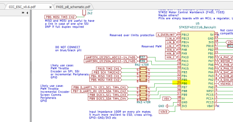
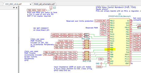
b.) This is when I suspected that the the signal was not getting to the pill so I checked that on the pill header itself, the signal is getting through. After some checking, I noticed that there's something not right with the MESC schematic. PB6 the pin for RCPWM is shown as pin 34
1763164864632.png

compared to the pill schematic shown below where it is connected to pin 33. There are other differences too as you can see.

1763164919048.png


So I connected the servo signal to pin 33 and .... it worked.! I could vary the speed by changing the pulse duration .

And my next question. If I want to connect a pwm encoder instead of rc pwm input , all I need to do is to make the change as shown below?

#define IC_TIMER htim4 //This must be TIM2-TIM5. Untested with other timers
//Assign a use for the input capture timer
// #define IC_TIMER_RCPWM
#define IC_TIMER_ENCODER

Many thanks again for the help.
 

Attachments

  • 1763164840774.png
    1763164840774.png
    156.2 KB · Views: 2
And my next question. If I want to connect a pwm encoder instead of rc pwm input , all I need to do is to make the change as shown below?

#define IC_TIMER htim4 //This must be TIM2-TIM5. Untested with other timers
//Assign a use for the input capture timer
// #define IC_TIMER_RCPWM
#define IC_TIMER_ENCODER

Many thanks again for the help.
Yes that's the hardware conf change required. You will of course need to physically have a pwm encoder on your motor and you'll need to set the pole pairs and work out the offset and relative direction. I'm not going to lie, this works out being quite tricky. You have to start by working out the sensorless spin direction, then with the encoder plugged in work out which way the encoder is by giving it a small turn and seeing if it goes up or down... Set the polarity bit accordingly... Set pp correctly... Set the offset correctly, this can be quite a faff. It basically involves guessing and changing the offset until it spins the correct direction with equal torque forwards and backwards, or setting a large d axis current and varying the offset until there's no resultant torque...

It's tricky. I might one day add an auto setup but it's sufficiently easy for me that I've never felt the trade-off of my time to make the auto setup vs the time it takes to just do it manually is worth it...
 
Well I guess when you contact a company asking for free help with another companies products, there's no great surprise when they don't answer...
No. I got an automatically generated message from mailer-daemon@googlemail.com. That's why it looks like an abandoned or not maintained website. They probably did not even see my email if they exist at all.

1763276602546.png
 
Last edited:
Back
Top