• Hello ES! We could use some help to get us past the finish line on building the new knowledgebase for the forum.
    Can you donate? Please see our fundraising page. Thank you!

Shadow Sabre 12FET High Power Controller (Looking for Feedback)

SymbyoteSystems

🔌 New-ish
Joined
Apr 28, 2026
Messages
25
Location
India
Hi everyone,

I’ve been working on a high-power motor controller focused on sustained load performance rather than just peak specs.

This is the Shadow Sabre 12FET, intended for applications like electric dirt bikes, high-power ebikes, scooters, skateboards and performance builds.

Key points:
  • 36V–126V Peak
  • 350A phase current
  • Designed with focus on thermal stability under continuous load
I’ve put together a page with details, here:
Shadowsabre

Also sharing a short initial test clip (bench run, no load):
12 FET Test Video .mp4

Currently testing on an ebike setup for behavior and response. More testing (load/thermal) in progress.

Would appreciate feedback from experienced DIY builders here—especially on:
  • thermal expectations
  • use cases you’d push this into
  • any critical features you look for
Happy to answer technical questions.
 
Wasn't sure there for a min what this was until I looked at the datasheet where the real details actually are. With that I have some more specific technical questions.
- Are you planning on adding the VESC hardware config and such to the VESC project so the firmware can be updated in the future and users don't get stuck on some old version?
- Can we see a picture of the board? Honestly I just want to see how the layout looks and how many and what type of filter caps there are. I want to know there is enough filtering so run motors well at high power in sensorless without noise being an issue. This is often the difference between a crap controller and a good one as it's for some reason something that gets cut to save money.
- Is it potted or waterproofed or water resistant enough?
 
Starting from a stop without stuttering seems tough for many controllers I try out.

A separate output for a brake resistor would be a nice plus that I see on servo controllers, but not ebike ones.

Every connector the Spitend add-on board adds would be nice too:

And all the stuff Grin does, like bidirectional throttle for proportional regen, virtual electronic freewheeling to make DD motors act like geared, supporting third party displays, etc..
 
@Shadowsabre This sounds great! Things that I think would make it competitive:
- Reasonably low price. Your main competitors are probably 3shul and VESC Labs, and while I'm sure they're good (especially VESC Labs), the prices are through the roof for an average hobbyist. At that point, the advantage of VESC loses its value compared to just getting a Fardriver for the fraction of the price.

- EV specific features. As @Inanek said, everything that the Spintend has would be amazing to have built-in on a VESC. The only sort-of-example we have yet are Flipsky's FT-series controllers--however, those use Flipsky's custom (and not near as good) firmware and app, negating the VESC advantage and making them no better than a regular controller except for size + sensorless. Having all the EV features on a real VESC would be something actually unique.

- Stocking on Amazon. I understand that this might be very impractical for a small company, but one of the reasons Flipsky does so well compared to other brands like Spintend that have better hardware is because Flipsky stocks their main controllers on Amazon. One can order a 75200 and have it arrive in a few days, which gets extremely appealing compared to ordering from China--weeks for shipping, unknown tariffs on top of the cost, customs... The ability for customers to have the VESC delivered from their same country has given Flipsky a large competitive edge on top of their cheaper prices.

- Hardware config/firmware released to VESC website. @scianiac already mentioned this, releasing the firmware to the VESC project is a big plus and both Spintend and Flipsky do this. Brands such as 3Shul and Electro & Co. do not, to the annoyance of users (Electro & Co doesn't even let you use the VESC tool AFAIK.)
 
Wasn't sure there for a min what this was until I looked at the datasheet where the real details actually are. With that I have some more specific technical questions.
- Are you planning on adding the VESC hardware config and such to the VESC project so the firmware can be updated in the future and users don't get stuck on some old version?
- Can we see a picture of the board? Honestly I just want to see how the layout looks and how many and what type of filter caps there are. I want to know there is enough filtering so run motors well at high power in sensorless without noise being an issue. This is often the difference between a crap controller and a good one as it's for some reason something that gets cut to save money.
- Is it potted or waterproofed or water resistant enough?
- Updated version will be available on the website support page in future.
- Sure I will post some photos here of internals
- This version is not waterproof ,, it just splashproof. Conformal coating is there only. No potting.
- For any other queries you can email me at info@shadowsabre.com or connect me on whatsapp through webpage.
 
So which "website" are you referring to there, your website or the VESC GITHUB?


We maintain our own firmware builds based on VESC 6.05 stable. Updated binaries and the hardware config files will be available for download on our website (shadowsabre.com/support) as we release updates.


We haven’t submitted the hwconf upstream to Benjamin’s repo yet. We’re open to it once we’ve completed validation on all three voltage classes and are confident the config is stable enough for the community to build against. We don’t want to push something upstream that’s still being tuned — that would create exactly the “stuck on old version” problem you’re concerned about.


In the meantime, flashing is straightforward — our .bin is a standard VESC 6.05 image, and VESC Tool connects over USB or Bluetooth (via our companion module) for all configuration. No custom tooling required.


On filtering and sensorless performance:


Since you specifically asked about this — the DC bus uses a combination of distributed ceramic decoupling at each switch position for high-frequency transient suppression, plus bulk electrolytic storage for energy reserve during load transients. Phase voltage sensing has hardware-switched low-pass filters (firmware-controllable, not hardwired) with a cutoff designed for clean sensorless observer performance at high ERPM.


Current sensing uses a precision instrumentation amplifier referenced to a dedicated 1.65V precision voltage source — not derived from the bus voltage, which is where a lot of cheaper controllers pick up noise. The PCB stackup separates analog and digital ground planes, joined at a single star point near the MCU’s analog reference pin.


We specifically designed for clean sensorless FOC at full power — it wasn’t bolted on after the fact. I’ll post board photos this week showing the layout so you can see it firsthand.


Happy to answer anything else. I’d rather over-share the engineering detail than leave questions open.
 
@Shadowsabre This sounds great! Things that I think would make it competitive:
- Reasonably low price. Your main competitors are probably 3shul and VESC Labs, and while I'm sure they're good (especially VESC Labs), the prices are through the roof for an average hobbyist. At that point, the advantage of VESC loses its value compared to just getting a Fardriver for the fraction of the price.

- EV specific features. As @Inanek said, everything that the Spintend has would be amazing to have built-in on a VESC. The only sort-of-example we have yet are Flipsky's FT-series controllers--however, those use Flipsky's custom (and not near as good) firmware and app, negating the VESC advantage and making them no better than a regular controller except for size + sensorless. Having all the EV features on a real VESC would be something actually unique.

- Stocking on Amazon. I understand that this might be very impractical for a small company, but one of the reasons Flipsky does so well compared to other brands like Spintend that have better hardware is because Flipsky stocks their main controllers on Amazon. One can order a 75200 and have it arrive in a few days, which gets extremely appealing compared to ordering from China--weeks for shipping, unknown tariffs on top of the cost, customs... The ability for customers to have the VESC delivered from their same country has given Flipsky a large competitive edge on top of their cheaper prices.

- Hardware config/firmware released to VESC website. @scianiac already mentioned this, releasing the firmware to the VESC project is a big plus and both Spintend and Flipsky do this. Brands such as 3Shul and Electro & Co. do not, to the annoyance of users (Electro & Co doesn't even let you use the VESC tool AFAIK.)


@ljbred08 Really appreciate this — this is exactly the kind of feedback that shapes what we prioritize. Let me address each point honestly.


Pricing:


We’re aware of the gap. The competition runs $400–600+ before shipping, and at that price point a lot of builders just default to a $60 Fardriver and accept the trade-offs. Our goal is to land significantly below the premium VESC brands while being properly engineered — not race-to-the-bottom cheap, but genuinely accessible for someone building a serious Sur-Ron class or high-power ebike. We’ll announce pricing closer to availability but “affordable VESC that doesn’t cut corners” is literally the design brief we started from.


EV-specific features:


This is where we’ve spent the most development time and I think you’ll find this interesting. The 12FET runs real VESC 6.05 firmware — not a custom fork that locks you out of VESC Tool like Flipsky’s FT series. On top of that, we’ve built a custom vehicle control layer that includes:


• 3 riding modes (ECO / SPORT / MANIAC) with configurable current and voltage scaling per mode — switchable via a physical toggle on the harness, no app needed mid-ride

• Direction reverse with a full safety interlock — speed must be below threshold, throttle at idle, 500ms confirmation hold before reverse engages, audible buzzer confirmation

• Safe start — motor will not engage if throttle isn’t at idle during power-on

• Key switch enable with an isolated low-voltage circuit — no high voltage on any signal wire (this is a genuine safety issue with Fardriver’s approach where the enable signal carries bus voltage)

• Speed signal output for aftermarket dashboards/speedometers

• Brake switch input with configurable regen behavior

• AUX outputs for radiator fan control, contactor, lights — whatever the build needs

• Bluetooth + WiFi companion module (CAN-linked) for wireless config and telemetry

• WS2812 RGB LED strip output for status, mode indication, underglow — it’s a small thing but builders love it


All of this runs through VESC Tool for configuration. No separate app, no proprietary lockout, no Flipsky-style firmware that breaks VESC compatibility.


Amazon / availability:


You’re absolutely right that Flipsky’s Amazon presence is a massive competitive advantage. We can’t match that on day one — we’re a small team and the logistics of Amazon FBA across multiple countries is a significant investment. Our initial plan is direct sales from our website with regional shipping from India, and we’re exploring fulfillment partnerships in the US and EU to cut delivery times. I won’t pretend we’ll have Amazon Prime shipping next month, but it’s on the roadmap because you’re right — if a builder can get a Flipsky 75200 in two days and ours takes three weeks from overseas, that’s a real barrier regardless of how much better the hardware is.


Hardware config on VESC project:


Agreed, and @scianiac raised this too. We’re committed to making the hwconf available — the question is timing. We want to finish validation across all three voltage classes (48V/72V/108V) before pushing anything upstream so the community isn’t building against a config that’s still changing. In the short term, firmware binaries and source are available from our support page. Upstream submission to the VESC project is planned once the config is locked.


To be clear — we use real VESC Tool, real VESC firmware, full compatibility. No proprietary lockout, no custom app requirement. If that’s important to you (and it sounds like it is), we’re on the same page.


Thanks for the detailed feedback. This is genuinely useful for prioritizing what we work on next.
 
Starting from a stop without stuttering seems tough for many controllers I try out.

A separate output for a brake resistor would be a nice plus that I see on servo controllers, but not ebike ones.

Every connector the Spitend add-on board adds would be nice too:

And all the stuff Grin does, like bidirectional throttle for proportional regen, virtual electronic freewheeling to make DD motors act like geared, supporting third party displays, etc..


@Inanek Great points — let me go through each one.


Smooth start from standstill:


I hear you — this is a common frustration with VESC-based controllers specifically, not just cheap sensorless ones. The stuttering usually comes from noisy current measurement at low duty cycle, poor hall sensor signal integrity, or a rough handoff from hall-based commutation to the sensorless observer.


We can’t claim sensorless startup from zero RPM — nobody can do that cleanly on a real vehicle load. What we focused on is making sure the sensor-based startup and the transition to sensorless are clean. That comes down to hardware — the current sensing has a dedicated precision voltage reference (not bus-derived, which drifts under load), analog and digital grounds are physically separated in the PCB stackup, and the hall sensor inputs have proper filtering and a clean 5V supply rail with bulk capacitance behind it. The result is that the FOC loop gets clean data from the first commutation step, so there’s no hunting or jerking at low speed.


We support hall sensors, SIN/COS analog encoder, and ABI quadrature — all of which give solid low-speed performance. The sensorless observer takes over once there’s enough back-EMF to track reliably. In our testing the transition is seamless, but I’d rather have builders confirm that on their own motors than make claims we haven’t validated across every motor type yet. Happy to share startup behavior once we have more motor test data.


Brake resistor output:


Honest answer — there’s no dedicated brake resistor output on this version. The two AUX outputs are open-drain rated at 2A, so you could drive a relay to switch a brake resistor through one of those using a LispBM script that monitors bus voltage during regen. It’s not the same as a dedicated high-current brake resistor FET, but it works for most builds. Noted as a feature request for the next hardware revision though — it’s a valid gap, especially for builds where the battery can’t absorb full regen current.


Spintend Ewheel adapter features:


This is actually where I think you’ll find the 12FET interesting — almost everything that Spintend sells as a $36 add-on board is already built into our controller natively:


• Horn / headlight / accessory outputs — 2x AUX open-drain outputs, 2A each. Wire a horn or light relay directly, no add-on board needed.

• Brake light trigger — dedicated brake switch input on the main connector. When brake is active, you can drive a brake light from an AUX output or through the RGB strip — configurable in firmware.

• Reverse light — direction state is tracked in firmware. Reverse engagement triggers the buzzer for audible confirmation and sets an internal flag that can drive an AUX output or change the WS2812 strip color (we already do a red tinge overlay on the RGB strip in reverse).

• 3-level throttle / riding modes — ECO / SPORT / MANIAC modes via a physical analog switch on the harness. No app needed, instant switching, smooth ramped transitions mid-ride.

• Motor reverse — built-in with a full safety interlock (speed below threshold + throttle idle + 500ms hold). Not just a direction flip — it’s a proper EV-grade reverse system with audible confirmation.

• Cruise control — this is a native VESC ADC app feature and works through VESC Tool configuration. No add-on needed.

• WS2812 RGB strip output — up to 8 LEDs, driven natively from the controller. Status, mode indication, fault alerts, reverse state — all built into the firmware state machine.


So where Spintend requires a VESC + their adapter board + wiring between both, the 12FET does it all from one connector with zero add-ons.


Grin features:


Bidirectional throttle with proportional regen is supported through VESC’s ADC app configuration — you can set it up in VESC Tool so one direction of the throttle is forward and the other is regen braking, proportional to how far you push it. Works out of the box.


Virtual electronic freewheeling to make direct-drive motors feel geared is a Grin-specific firmware feature that isn’t part of standard VESC. We don’t have that currently, but it’s an interesting idea worth looking into.


Third party display support — we have both CAN bus and UART broken out on the main connector. Protocol compatibility depends on which display you’re targeting, but the hardware interface is there for displays that speak VESC CAN protocol or serial.


The short version: most of what you’d need an add-on board for on other VESC controllers is already integrated into the 12FET. One board, one connector, one firmware. That was the design goal from the start.
 
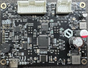
Some board photos as promised. Wanted to share the hardware properly since a few of you asked about filtering, layout, and build quality.


Control board overview:
IMG_4864.jpg

This is the top side of the control board. MCU in the centre, power supply chain on the right (you can see the bulk electrolytics for the 12V and 5V rails), signal conditioning and communication interfaces spread across the board. USB-C on the bottom left for direct VESC Tool connection. The six-pin header on the top left is SWD for firmware development — yes, we flash and debug our own firmware directly, not just loading someone else's binary.


Two connectors along the top — 24-pin main connector (throttle, CAN, UART, AUX, modes, switches) and 10-pin sensor connector (hall, SIN/COS, motor temp). Everything breaks out to these two connectors, no loose wires hanging off the board.
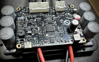
Full assembly — control board on power stage:
IMG_4870.jpg


This is how it comes together. The control board sits above the power stage. The six large cylindrical caps around the perimeter are the bulk DC bus electrolytics — energy storage for load transients. Phase wires (black, 8AWG) and battery wires (black & red 12AWG x2) come off the power stage below. The aluminium baseplate underneath the power board is the thermal interface — MOSFETs dump heat directly through the aluminium-core PCB into whatever heatsink or chassis you mount it to.

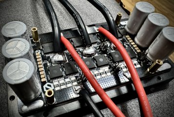
Power stage close-up:
IMG_4867.jpg

The MOSFETs are in TOLL packages, two paralleled per switch position, twelve total across the three-phase bridge. Between the FET positions you can see the small ceramic capacitors distributed right at each switching node — these are the high-frequency DC bus decoupling caps that keep the voltage clean during hard switching transitions. This is the filtering that matters for sensorless performance — if these aren't close to the FETs and there aren't enough of them, switching noise couples into the current and voltage sensing and your FOC observer gets garbage data. It's the single most common cost-cutting move on cheap controllers and it's the reason sensorless performance varies so much between boards that technically run the same firmware.


The current sense shunts are the four small resistors in a row between each FET pair and the phase output — four paralleled per phase. More shunts in parallel means lower effective resistance (better efficiency, less heat in the sense path) and also spreads the power dissipation so no single shunt is thermally stressed. The precision instrumentation amplifier on the control board reads across these.


The bulk electrolytic caps along both edges handle the low-frequency energy storage — keeping the bus voltage stable when the motor pulls hundreds of amps during acceleration.


A note on build quality: What you're looking at is a hand-assembled prototype — the solder on the heavy phase wire connections is functional but not pretty. Production units will use machine placement for all SMD components and proper fixtures for the power connections. The circuit and PCB layout are final, which is what matters at this stage.


I know a few of you also asked about waterproofing — this board gets conformal coated on the control side for splash protection. The power stage relies on the enclosure for environmental protection. No potting on this version, but the enclosure has gasket provisions for aftermarket sealing if your application needs it.


More testing updates coming as we get further into motor validation. Happy to answer anything about what you're seeing here.
 
Last edited:
We support hall sensors, SIN/COS analog encoder, and ABI quadrature — all of which give solid low-speed performance. The sensorless observer takes over once there’s enough back-EMF to track reliably. In our testing the transition is seamless, but I’d rather have builders confirm that on their own motors than make claims we haven’t validated across every motor type yet. Happy to share startup behavior once we have more motor test data.
Does that also include SPI encoders? I kinda assumed so because it's in VESC by default and the only way it wouldn't is if your put non-bypassable filters on the hall inputs. Although with SIN/COS encoders being less noise sensitive they are a perfectly fine option as well, but both options would be good.

So far though your openness and commitment to VESC has impressed me and I'm excited to see these get to market. I think your your market target is sound, there is not point in trying to compete with Flipsky on price but can do well being a bit cheaper than VESCLabs. But I think you need to nail the reliability and stable performance. Like even a high power Flipsky is enough money that you're annoyed if it doesn't work or blows up and wish you paid more for something that works.

There are more high power options out there now but a few years ago it seemed 3Shul was the only really high power VESC option and a lot of people bought them, had issues, often with firmware and tuning that they couldn't fix and 3Shull wouldn't help. But they still felt like that was their only VESC option in that power range. Like I said there are more options now but high power, and specifically higher voltage options are still limited and there is demand.

Thanks for the photos, I'm not expert but at a glance looks like a solid design to me, caps and stuff in the places I want to see them. And yeah it looks like the enclosure could be lightly modified for another layer of water resistance and that combined with the conformal coating and not putting it somewhere where it's going to actually get wet should be enough. Potting can be a double edged sword I think I prefer no potting, means you can repair and troubleshoot if needed, saves weight and makes it more flexible.
 
Does that also include SPI encoders? I kinda assumed so because it's in VESC by default and the only way it wouldn't is if your put non-bypassable filters on the hall inputs. Although with SIN/COS encoders being less noise sensitive they are a perfectly fine option as well, but both options would be good.

So far though your openness and commitment to VESC has impressed me and I'm excited to see these get to market. I think your your market target is sound, there is not point in trying to compete with Flipsky on price but can do well being a bit cheaper than VESCLabs. But I think you need to nail the reliability and stable performance. Like even a high power Flipsky is enough money that you're annoyed if it doesn't work or blows up and wish you paid more for something that works.

There are more high power options out there now but a few years ago it seemed 3Shul was the only really high power VESC option and a lot of people bought them, had issues, often with firmware and tuning that they couldn't fix and 3Shull wouldn't help. But they still felt like that was their only VESC option in that power range. Like I said there are more options now but high power, and specifically higher voltage options are still limited and there is demand.

Thanks for the photos, I'm not expert but at a glance looks like a solid design to me, caps and stuff in the places I want to see them. And yeah it looks like the enclosure could be lightly modified for another layer of water resistance and that combined with the conformal coating and not putting it somewhere where it's going to actually get wet should be enough. Potting can be a double edged sword I think I prefer no potting, means you can repair and troubleshoot if needed, saves weight and makes it more flexible.
@scianiac Really appreciate the detailed feedback — and glad the board photos answered some of your questions about filtering and build quality.

On SPI encoders:
This version doesn’t support SPI encoders directly. The hall/encoder pins are filtered for noise immunity, and the available UARTs are allocated to BLE and general communication.
What we do support on the current sensor connector:
• Hall sensors — standard digital halls, the most common sensor in Sur-Ron, Talaria, and hub motor builds
• ABI quadrature encoder — runs through the hall pins (A/B/Z on U/V/W), encoder PWM output goes to RC_PWM input. Select encoder type in VESC Tool and it configures automatically
• SIN/COS analog encoder — dedicated analog inputs on the sensor connector. Best noise immunity of any encoder interface for high-power FOC
• Sensorless — back-EMF observer, no external sensor needed
For builders who specifically want SPI absolute encoders (AS5047P, TLE5012B, etc.) — we’ve heard this from multiple people already and it’s designed into the next hardware revision. The sensor connector goes from 10-pin to 12-pin, adding dedicated MISO, SCK, and CS lines. Same controller, same main connector, same firmware — just two extra pins on the sensor side.
So SPI is coming but not on V2.0. In the meantime, ABI through the hall pins gives you incremental encoder support out of the box, and SIN/COS gives you absolute position with the best noise performance.

On pricing and positioning:
You’ve basically described exactly where we’re aiming. We’re not trying to be the cheapest — that race to the bottom is how you end up with boards that blow up and give VESC a bad reputation. The goal is reliable out of the box, at a price that doesn’t make you agonize before clicking buy. Meaningfully below competition, but with build quality and features that justify every dollar over a Flipsky.

On reliability:
This is what we’re most focused on and I appreciate you calling it out directly. Doesn’t matter how many amps the spec sheet claims if the board dies after three rides. That’s why we’re validating properly before shipping — sustained thermal testing (not just peak for two seconds), boot-time offset calibration, hardware protections that can’t be bypassed by bad config, and a safe power-on circuit that keeps high voltage off signal wires. We’d rather ship later with a controller that doesn’t come back than ship early and deal with returns.

On waterproofing:
Agreed — no potting is intentional. Potted boards can’t be diagnosed or repaired, and as you said it’s a double edged sword. Conformal coating on the control electronics plus a sealed enclosure is the right approach. The enclosure has gasket provisions for aftermarket sealing if someone needs more, but we’re not going to pot it and make it a throwaway.

On high voltage demand:
Good to hear that confirmed from the community. Our 108V class (up to 126V bus) is targeting exactly the gap you’re describing. Most VESC options max out around 75–84V, and the few that go higher are either very expensive or have reliability questions. We want the 108V variant to be the obvious choice for anyone running 26S–30S.


Thanks for the honest assessment of the hardware. This kind of feedback from experienced builders is what shapes a better product.
 
How are the mosfets cooled?
The MOSFETs are mounted on an aluminum-core PCB — they dump heat directly through the board substrate into the aluminum base, which acts as a built-in heatsink. You mount the controller with the aluminum baseplate against your chassis, frame, or an external heatsink, and that’s your thermal path.
No fans, no liquid cooling required for rated continuous current. The aluminum base gives you a flat mounting surface — bolt it to any metal structure on your build and you’ve got passive cooling. Add a fan blowing across the heatsink and you get roughly 15–20% more continuous current headroom. Liquid cold plate underneath would push it further if your build supports it.
 
Quick update — got the first real-world test on video of 12FET on Electric Motorcycle.


This is a brake stall test on an actual bike — full throttle against locked brakes, forcing the motor to stall and pushing current to the configured limit. No bench fans, no ideal conditions, just the controller on a real vehicle doing the hardest thing you can ask it to do short of a dyno.


Results:
  • 350A phase current sustained — controller held it clean, no faults, no thermal cutoff
  • BMS tripped at 200A battery — the battery pack gave up before the controller did
  • Zero stuttering, zero shutdown, zero drama

Also showing the three riding modes (ECO / SPORT / MANIAC) switching live and the reverse engagement with the safety interlock — you can see the delay and buzzer confirmation before reverse activates.


This is prototype hardware with hand-soldered phase wires — production units will be cleaner but the electronics and firmware are final.


Happy to answer questions on anything you see in the video.
 
So I have held off commenting for a few days, your PCB looks pretty sensible. It has the right things in the right place for a 12 FET, layout looks tidy and reasonable... yet something has seemed a bit strange to me though. Let me elaborate:

1) you are selling all sorts of absolutely run of the mill things as being spectacular - precision current amplifier, precision voltage sources, high accuracy etc... when you have INA(4)181, which is about the most standard amplifier as used on... most... low side shunt VESC boards, spintend, flipsky... 3shul tried and trusted but unremarkable, Fortior FD6288Q gate driver... again tried and trusted, but as used on many western and chinese boards... and... 3Shul... and TOLL MOS on IMS. No part on it is remarkable. The DCDCs are normal. Good cost effective parts. Not special, not revolutionary.
2) The layout... this is a concept identical to the IMS board I posted on here (GaN and IMS MESC controller boards) waaay back before IMS became the mainstream in China VESCs, and now pretty much the standard Chinese arrangement... And 3shul. A few months after I posted my IMS board design, Flipsky et al came out with IMS boards. Fardriver were quietly ahead of me. Another year later, Torp, EBMX etc came out with the same design... with a few extra MOSFETs. At this stage, this is 100% normalised.
3) You have a lot of nice input protections on the big connectors. I rarely see that on Flipsky, Spintend occasionally puts them on, VESC labs uses them... You have the same input and protections as... 3Shul.
4) The descriptions of the power capability... designed for continuous in mind... well it's not going to work substantially differently from the other 12 FET TOLL on IMS with fd6288 gate driver designs.

In fact, the similarity is so great, it looks to me like you have gotten hold of a 3shul C350 and exactly replicated it, which is not a bad option, of the VESC clones, for years 3Shul has been one of the few innovators and only sellers of high voltage boards, but there's no improvement over it I can see, it looks like a clone, and the core power stage of a 3Shul C350 is nearly identical to a flipsky or spintend.

So yeah, nice, tidy etc but there is no magic that will make this somehow vastly better...
 
So I have held off commenting for a few days, your PCB looks pretty sensible. It has the right things in the right place for a 12 FET, layout looks tidy and reasonable... yet something has seemed a bit strange to me though. Let me elaborate:

1) you are selling all sorts of absolutely run of the mill things as being spectacular - precision current amplifier, precision voltage sources, high accuracy etc... when you have INA(4)181, which is about the most standard amplifier as used on... most... low side shunt VESC boards, spintend, flipsky... 3shul tried and trusted but unremarkable, Fortior FD6288Q gate driver... again tried and trusted, but as used on many western and chinese boards... and... 3Shul... and TOLL MOS on IMS. No part on it is remarkable. The DCDCs are normal. Good cost effective parts. Not special, not revolutionary.
2) The layout... this is a concept identical to the IMS board I posted on here (GaN and IMS MESC controller boards) waaay back before IMS became the mainstream in China VESCs, and now pretty much the standard Chinese arrangement... And 3shul. A few months after I posted my IMS board design, Flipsky et al came out with IMS boards. Fardriver were quietly ahead of me. Another year later, Torp, EBMX etc came out with the same design... with a few extra MOSFETs. At this stage, this is 100% normalised.
3) You have a lot of nice input protections on the big connectors. I rarely see that on Flipsky, Spintend occasionally puts them on, VESC labs uses them... You have the same input and protections as... 3Shul.
4) The descriptions of the power capability... designed for continuous in mind... well it's not going to work substantially differently from the other 12 FET TOLL on IMS with fd6288 gate driver designs.

In fact, the similarity is so great, it looks to me like you have gotten hold of a 3shul C350 and exactly replicated it, which is not a bad option, of the VESC clones, for years 3Shul has been one of the few innovators and only sellers of high voltage boards, but there's no improvement over it I can see, it looks like a clone, and the core power stage of a 3Shul C350 is nearly identical to a flipsky or spintend.

So yeah, nice, tidy etc but there is no magic that will make this somehow vastly better...
@mxlemming Appreciate you taking the time to look at this properly before commenting. You clearly know what you’re looking at and I’d rather get a straight critique than empty encouragement.
You’re right on the components. The current sense amplifier, gate driver, MOSFETs, DC-DC converters — these are standard, proven, cost-effective parts. I won’t dress them up as something they’re not. They’re the right parts for this topology and that’s why everyone building in this space converges on similar choices. If my earlier posts gave the impression I was presenting standard engineering as breakthrough innovation, that’s a fair call-out and I’ll tighten up the language.
On the layout — same thing. When you’re doing a 3-phase bridge with low-side shunts on an aluminum substrate in TOLL packages, the physics of the problem narrows the solution space. FETs along the edge for thermal path, bus caps distributed at each switch position, shunts between FETs and phase output, control board stacked above. That’s not convergence by coincidence, it’s convergence because it’s the correct answer. I’d be worried if my layout looked dramatically different from proven designs — that would probably mean I’d gotten something wrong.
I designed this from scratch in KiCad, but I fully accept that the result looks familiar, because the same constraints produce similar solutions. I’m not claiming to have reinvented the power stage.
Where I think this board does bring something — and where I should have focused the conversation from the start instead of talking about parts — is the integration and the firmware layer sitting on top of the hardware.
On the hardware integration side: the power-on architecture doesn’t route high voltage through the signal connector. The bus comes in, goes straight to the power stage and to the DC-DC chain on board. The enable circuit is a low-voltage key switch through a dedicated FET circuit that’s designed to be immune to accidental activation — static, body contact, EMI. The signal connector carries nothing above 5V. That’s a conscious choice because this controller is going into vehicles where signal harnesses run alongside riders, get pulled, get wet, get damaged. Keeping high voltage off the harness is a safety decision, not a spec sheet feature.
On the firmware side — this is where most of the development time went. It’s not a stock binary with a hardware config. We’ve written a custom vehicle control layer: three configurable riding modes with ramped transitions so there’s no sudden torque change mid-ride, direction reverse with a multi-stage safety interlock (speed check, throttle idle, confirmation hold, audible feedback before reverse engages), safe start that blocks motor engagement if throttle isn’t idle at power-on, sensor fault detection, and a set of scripting extensions for builders who want to customize further. All accessible through standard configuration tools, no proprietary lockout.
The integrated I/O is the other piece — two AUX outputs, brake input, direction switch, ignition detect, mode switch, speed output, RGB LED strip, buzzer — all on a single connector. Most of the peripheral functionality that would normally require an adapter board or external wiring is handled natively by the controller.
So to your core point — is the power stage revolutionary? No. It’s a well-executed version of a proven topology using known parts. I agree. The value isn’t in the power stage being magical. It’s in the complete package: the firmware, the safety architecture, the integrated I/O, the fact that it works out of the box as a vehicle controller rather than just a motor driver, and the price it comes in at.
Whether that’s enough differentiation is for the market to decide. But I’d rather be straight about what this is than let the marketing get ahead of the engineering.
 
Really appreciate the technical discussions, suggestions, and feedback from everyone here over the last few days after we shared the SHADOW SABRE 12FET internals and hardware details.

A lot of the comments and questions genuinely helped us look at things from a builder’s perspective, which is exactly why we wanted to share the project openly with the community from the beginning.

Because of that, we’ve decided to open a small early-access batch of the SHADOW SABRE 12FET for a few serious builders and enthusiasts interested in real-world testing and evaluation.

This is not intended to be a big sales launch or mass-production release yet.

The goal is mainly:
  • Real-world validation
  • Different build integrations
  • Honest community feedback
  • Long-term improvement of the platform
The controller is currently available in:
  • Base Model
  • Race Spec Version
Current platform details:
  • Up to 126V platform
  • Compact high-current 12 FET architecture
  • CNC aluminum housing
  • Conformal coated electronics
The early-access batch also includes the SYMXPRESS Bluetooth programming module, developed by our team for wireless programming and communication with the controller platform.

Both the controller and SYMXPRESS module are currently available under the early-access program, and the datasheet/specifications are available on the webpage.

We’d especially love to see the controllers used in interesting DIY builds and pushed in real conditions by experienced users from the community.

Early users will receive direct setup and tuning support from our side, and in return we’d appreciate genuine feedback, testing observations, and build updates shared back with the community here.

Limited early-access batch is now open.

Pre-order / details:
SHADOW SABRE 12FET
 
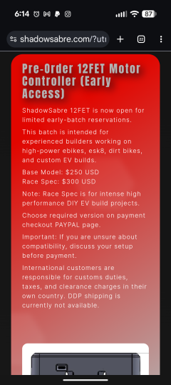
That's impressive the price came in under a Phaserunner:
Screenshot_20260508-061420.png
Although a bit more than the cheapest Spitend + e wheel ADC adapter board + Bluetooth module.

Too bad it's a bit overpowered for me. Just 50A is enough for me to hit 30mph and have the police pacing me in cruisers to check if I'm pedaling. Otherwise I'd buy 👍
 
That's impressive the price came in under a Phaserunner:
View attachment 388012
Although a bit more than the cheapest Spitend + e wheel ADC adapter board + Bluetooth module.

Too bad it's a bit overpowered for me. Just 50A is enough for me to hit 30mph and have the police pacing me in cruisers to check if I'm pedaling. Otherwise I'd buy 👍
On the power level — totally fair. The 12FET is built for the high-power crowd, and if your build only needs 50A then this is way more controller than you need and you shouldn’t overspend for headroom you’ll never use.
That said — a smaller variant is on the roadmap. Same firmware, same features, same ecosystem, just sized for lighter builds where 50–100A and compact packaging matters more than peak current. No timeline yet but it’s coming.
If you ever decide to build something angrier though, you know where to find us.
 
Small update from our side.

In this short video, we are running two Shadow Sabre 12FET controllers with two hub motors using a single throttle input.

Video link:

Both controllers are connected through a CAN sync harness, with one controller acting as the main control side and the second controller following through CAN communication. We are also using a single Bluetooth module for setup and monitoring.

The purpose of this test is to validate a practical dual-drive setup for compact EV applications, especially performance scooters and similar vehicles where dual hub motors are common.

This type of setup can be useful for builders who want:
  • Dual motor synchronization
  • One throttle control
  • Cleaner wiring through CAN sync
  • Bluetooth-based tuning and monitoring
  • Compact controller packaging for limited mounting space
We are still testing and improving the setup, but the early results are promising.

Would be good to hear feedback from builders who have worked with dual hub motor scooter or e-bike setups. What are the main problems you usually face in dual controller installations — throttle matching, wiring, tuning, heat, or display integration?
 
Has anyone purchased one of these yet? I've had someone reach out to me on facebook about them. I doubt I'll purchase one since there's no US distributor for them.
 
Amazon / availability:


You’re absolutely right that Flipsky’s Amazon presence is a massive competitive advantage. We can’t match that on day one — we’re a small team and the logistics of Amazon FBA across multiple countries is a significant investment. Our initial plan is direct sales from our website with regional shipping from India, and we’re exploring fulfillment partnerships in the US and EU to cut delivery times. I won’t pretend we’ll have Amazon Prime shipping next month, but it’s on the roadmap because you’re right — if a builder can get a Flipsky 75200 in two days and ours takes three weeks from overseas, that’s a real barrier regardless of how much better the hardware is.

I'm not worried about 2 day delivery, Amazon sucks for me anyhow being a week out. What I worry about is all the tariff nonsense I have to deal with in the USA. I was burned last year for some PCBs that I paid $200 for, then got SLAMMED for $370 in tariffs over.

I'd order one of these 48fet controllers right this moment, if you had some stateside retailer/reseller. Be it Amazon, a brick and mortar retailer, maybe ebay. If the price I paid was all there and known without the unpleasant surprise of how much it will end up costing me.

I wanted to buy a 3shul CC1000 controller, but this barrier has prevented that from happening as well. I believe if one of you had some sort of US based retail/resale to eliminate tariffs/logistics to US buyers, that'd instantly propel one of you ahead of the other.
 
I'm not worried about 2 day delivery, Amazon sucks for me anyhow being a week out. What I worry about is all the tariff nonsense I have to deal with in the USA. I was burned last year for some PCBs that I paid $200 for, then got SLAMMED for $370 in tariffs over.

I'd order one of these 48fet controllers right this moment, if you had some stateside retailer/reseller. Be it Amazon, a brick and mortar retailer, maybe ebay. If the price I paid was all there and known without the unpleasant surprise of how much it will end up costing me.

I wanted to buy a 3shul CC1000 controller, but this barrier has prevented that from happening as well. I believe if one of you had some sort of US based retail/resale to eliminate tariffs/logistics to US buyers, that'd instantly propel one of you ahead of the other.
That is a completely valid concern, and honestly this is one of the biggest barriers for US buyers right now.

For high-value controller hardware, the issue is not only shipping time — it is the uncertainty of the final landed cost. If someone pays for a controller and then later gets hit with unexpected customs, tariff, or clearance charges, that creates a bad buying experience even if the hardware itself is good.

So yes, I agree with you: having a US-based retail/resale option would make a major difference.

Our current direct-sales route is from India, and for standard international orders we have to be transparent that customs, duties, taxes, and clearance charges can depend on the destination country and shipping method.

Meanwhile, we are also actively working on US-based dealer / distributor options to solve this issue properly for future buyers. A local US buying route would make the process much easier for customers who do not want to deal with international customs uncertainty.

That said, for the 48FET specifically, if you are seriously interested, we can check a fixed DDP delivered-cost option for your US address.

That means we would calculate a final delivered price in advance, and the customs clearance / duty handling would be managed from our side so you do not get a surprise bill after the controller arrives.

I do not want to make a broad public promise until we calculate it properly, because the final number depends on shipping route, destination, declared product details, and logistics cost. But for a serious 48FET buyer, we can prepare a fixed landed-cost quote and make the buying process cleaner.

If that works for you, you can connect with us on WhatsApp (+91 7014043771) and share your state / ZIP code, battery voltage, motor setup, and the 48FET configuration you are considering. We can guide you better and confirm whether a DDP route makes sense before payment.
 
Quick update — uploaded a brutal test video over the weekend.

72V stage and 108V stage, back to back. Same controller, same encoder setup, just the bus voltage class swapped in VESC Tool config. Pushed it to 200A battery / 350A phase in MANIAC mode with passive cooling only (aluminum-core PCB, no fan, no liquid).

Goal was to see where the controller actually starts to misbehave under real load, not just bench-validate the spec sheet.


A few things I'd appreciate this group's eyes on, since this thread has had the most technically useful feedback so far:

→ Are there tests you'd want to see that I'm not showing? Long-duration thermal under sustained phase current, regen behavior under different load profiles, fault recovery — anything you'd consider essential for trusting a new controller at this power level.

→ ABI encoder setup — I went with quadrature through the hall pins (A/B/Z on U/V/W) with the encoder PWM into RC_PWM. Curious if anyone here has compared this to SIN/COS analog for noise immunity at high phase currents. My read was SIN/COS is more robust under EMI but ABI is more accurate at high RPM — would love to hear from anyone who's actually run both.

→ Methodology critique in general — I'm building hardware first and learning the deeper firmware/tuning side as I go. If I'm testing wrong or missing something obvious, tell me.

Also still offering: if any of the established builders here want a unit for independent testing, happy to send one. Honest feedback (good or bad) is worth more than anything I can say in a thread.

Thanks for the patience as we work through this.
 
Back
Top