Crossposted to the CA repair thread
http://www.endless-sphere.com/forums/viewtopic.php?p=676208#p676208
Having been too brain-dead to even solder wires to a controller here:
http://www.endless-sphere.com/forums/viewtopic.php?p=676199#p676199
and then also get so distracted I even burned dinner, I should have known better than to try to do anything else tonight, but no, I had to try to play with the new toy--the V3 CA.
After some hand, knuckle, elbow, forehead, and knee bangs and scrapes and dents, I managed to get the cranks off, and the old plain BB out (which was very difficult; the weather change to the cold pouring rain presently going on outside is making all my joints ache badly, so it's pretty hard to grip tools tightly enough). Then I cleaned out all the icky sandy grease out of the BB shell with ammonia and a brush, which was easy enough, but time-consuming.
I had a lot of trouble getting the Thun BB installed, though--it took another half hour or more to realize that despite the markings on the BB for "L" and "R", it couldn't possibly go in that way becuase the plastic caps are threaded the other direction from the BB shell on this bike. Maybe Magna welded the BB shell on backwards? I dunno. Anyway, so I installed the BB the only way it'll fit.
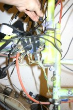
To install it's wiring, I had to take the plug off the cable, because the only holes in the BB are barely bigger than the wire. The only one I can actually use is the one in the bottom that's threaded for a screw that normally holds the plastic "brace" for shifter/brake cables, so that's how I ran teh cable out.
View attachment 7
There is a little break in the outer jacket of the cable, with some damaged insulation on the wires, so I cut some heatshrink to slide over it, but when I put it on there I couldn't get the BB in--too tight a fit. So I cut the heatshrink off, and ran teh cable thru, intending to slip a new piece thru the hole over the break in the wires' insulation (which happens to be right at the hole itself, where it could potentially touch the metal of the bike, which is at pack ground). But apparently I got distracted at some point and forgot to do that....

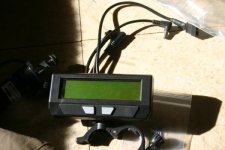
Then I clamped the CA to the steering extension stem tube, just below the stem clamp, so I could use both CAs at the same time and compare readings, etc., with teh old one as a standalone with speedo sensor, and the new one as a direct-plugin. It puts the new one a little lower than I'd like, but it was easier to clamp there than on the bars, as my bars are too thin for either CA's clamp to hold onto without adding something over them that's pretty thick, but the extension tube is just about right.
View attachment 5
The new CA's backlight is much dimmer than the old, and more yellow-orange where the old is white. I'm not sure if I like taht or not; I'll have to ride with it at night for a while to see if it's really bright enough, in traffic with headlights in my face.
I used the 6-wire DP extension cable to hook up the controller's known-working DP port (already tested with the other CA recently) to the new CA's DP port, and powered the bike up without problems, and the new CA also powered up fine, booted, and I went thru the screens and reset things to match this bike. Moved the throttle cable from the controller's input to the CA's input, and verified the CA sees it and reads it's voltages correctly.
That's actually a nice feature to be able to see the voltage and the little throttle indicator on the main screen going up and down-- would make troulbeshooting throttle issues a lot easier.
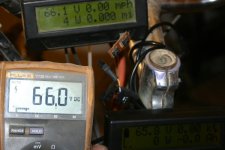
Voltage reading of the pack is a little differetn on the new CA, but it is just as likely something like voltage drop across connectors, or something int eh DP connector vs the shunt connector as anything else--it's only 0.03V. The Fluke DMM reads 66.0V at the back of the andersons into the controller, where the CA-SA reads 66.1V at the shunt between the pack andersons and the controller andersons, and the CA-DP reads 65.8V from the wires inside the controller.
However, there is quite a gap between the CA and the connectors for either the Thun BB sensor or the controller's throttle input, so I dug out the JST shells and pins that Bikefanatic sent me in the last care package, and made up an extension cable for the BB sensor (5-pin), and hooked it up, then powered on the bike again to make sure this cable worked before starting on the throttle extension.
This is where stuff really went sideways.

At first it seemed normal, but nothing was detected from the BB, moving it either direction, with or without a load (holding hte brake and pushing on a crank hard, for instance). Then the CA screen flickered, and it rebooted, tehn again, then it went blank and no backlight.
I switched the bike off and checked the plugs; it was definitely not a loose connnection. Since it all worked until I hooked up the BB sensor, I unplugged that, and tried again, to no avail. Hooked up throttle back to controlelr and verified it still worked. Disconnected CA from extension and hooked directly to controller, no change. Same thing hooking it to the shunt off teh older CA.
So I disconnected everything and opened it up, hoping for a broken wire inside, but as soon as I cracked the case I could smell that fried odor.

Most likely something at the sensor wires shorted to the bike frame, grounding out something inside the CA that isn't protected from such a fault, because I forgot to put that stupid heatshrink over the damaged-insulation wires on the BB sensor cable.

Nothng visible, so I checked input voltages with it hooked back to teh DP plug, and get pack voltage on the inptu wires like I should, and on the regulator transistor tab, but nothing at all on it's output.

So at a minimum, that transistor is probably toast, but it might be worse--it could be fine but something else, like the MCU, could be fried and pulling power down to nothing at the output. With my luck, that's what's wrong.
Anyway, I stopped there, because I can't hold the meter leads steady enough and am afraid I'll end up breaking a part off the board or shorting between pack voltage and something else that cna't take it, and making it even worse.
So for now, I can sleep easy knowing I've murdered a CA V3 faster than probably anyone else in the whole beta program. :lol:


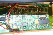
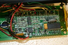
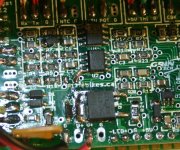
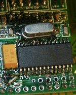
Some pics of the PCB inside the CA, in case anyone sees something fried that I missed, that might help me narrow down the problem and fix it. (assumign I even *can* fix it).
Crossposted to the CA Repair Thread.


