Adaptto Mini-E/Max-E Owner's Thread

ridethelightning said:
Allex said:
My domino worked perfectly without the resistor, calibration went fine, but Noticed a few things. First, i could not get autodetect to work the motor vibrated during first sequence and my speed jumped from normal 40kmh to 250kph. I thought it was something wrong with the controller so I swapped it out for another one. With it I could not get my magura to work at all, when doing autodetect i kicked back with "interrupted by thr" so I swich back to my first controller where thw throttle worked, but now it was the very same thing, interupted by theottle and on top of that I could not calibrate it. Anyway, the resistor trick solved all of this!

well, just want to say with all my adaptto experience, from good ol' rc7b right through to rc9e,perhaps 8 controllers, all using domino or magura, have never had an issue on set-up, no resistors required.

dominos are still going strong, but the maguras over time have seemed to develop issues with their output signal of one sort or other(errattic or reduced range)
so have swapped out for dominos. i still have not really studied the maguras(2) that went defective to see what went wrong yet.


brumbrum said:
I am thinking of jumping onto a group buy for a v3 mxus turbo motor for off-roading with.
The mxus 3t and 4t are both on Justins simulator. The 4t will make (on level ground with 23" outer diameter tire/17" wheel on level ground) 40mph with 83v ., and the 3t will be 47mph. The 4t slows down considerably on hills(a bit too slow for me)but of course it makes a lot less wasted heat than the 3t.
Heres the choice.... Would i be better off getting the 4t slower wound motor and using OVS to increase speed? I am guessing OVS will effect efficiency but does this mean it will create more heat? Or more heat than the 3t with no ovs?
So what should i do?
3t and no ovs or 4t with ovs?

Again, for off roading only.
,

+1 I was also wondering about this with the qs 9kv vs 10kv.
i dont like the drag feeling when coasting down hill, wondering if there would be noticable improvement with a 10 kv?

Well, i have preordered a 3T mxus v.3, something just a little different to the cro. So i guess i will have to wait and see how it compares.
 
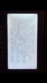
so now I got !Halls! on the screen and I am trying to do testing to find out if anything I can do to fix it.
As the first step most people do is checking voltage changing from 0V , 5V on black - to Red + and other 3 signal wire
While I start measuring, I got -0.10 V on the black and red, thats also same as what I got when measured V directly coming out form the controller positive and negative. I supposed I should get 5V.
Does that mean something wrong with my controller?
here is my screen on the display, strange thing is it shows
Vhall: 4.6V
any idea?
image.jpg
 
Uh oh BC Tech. Yeah, I think something shorted and got your resistor inside the compound controller. I'll leave it to the experts to confirm.


On a separate note, does anyone else have trouble with the display brightness at night? The bright screen is really distracting and when I look down at it, I have trouble adjusting back to the dark trail for a split second. I generally just try to ride forward when it isn't in my field of view but that defeats the purpose.

I have considered gluing on a Velcro cover to cover it up at night. Anyone else have this problem and/or a solution?
 
Mammalian04 said:
On a separate note, does anyone else have trouble with the display brightness at night? The bright screen is really distracting and when I look down at it, I have trouble adjusting back to the dark trail for a split second. I generally just try to ride forward when it isn't in my field of view but that defeats the purpose.
I haven't ridden much at night yet with my Adaptto, but did find it a little annoying when riding the other day as the sun was setting.
I assume you've tried setting the brightness from High to Low? That would be my first suggestion.

Cheers
 
Mammalian04 said:
Yes, brightness low.

i cannot echo that i'm disturebed by the display set to "low brightness"
But something, that some people consider as BUG, could solves this in your case.
So, i have a 5 Watt bikelight installed and connected to the USB-Plug.
when i switch on the light around 1 Amp gets drawn trough the USB, and the display backlight gets "dimmed"

notger
 
Mammalian04 said:
Uh oh BC Tech. Yeah, I think something shorted and got your resistor inside the compound controller. I'll leave it to the experts to confirm.


On a separate note, does anyone else have trouble with the display brightness at night? The bright screen is really distracting and when I look down at it, I have trouble adjusting back to the dark trail for a split second. I generally just try to ride forward when it isn't in my field of view but that defeats the purpose.

I have considered gluing on a Velcro cover to cover it up at night. Anyone else have this problem and/or a solution?

Thanks Mammalian04. Am I supposed to get 5V from the controller to the plug on the red (positive) and black (negative) wires?
 
BCTECH said:
Mammalian04 said:
Uh oh BC Tech. Yeah, I think something shorted and got your resistor inside the compound controller. I'll leave it to the experts to confirm.


On a separate note, does anyone else have trouble with the display brightness at night? The bright screen is really distracting and when I look down at it, I have trouble adjusting back to the dark trail for a split second. I generally just try to ride forward when it isn't in my field of view but that defeats the purpose.

I have considered gluing on a Velcro cover to cover it up at night. Anyone else have this problem and/or a solution?

Thanks Mammalian04. Am I supposed to get 5V from the controller to the plug on the red (positive) and black (negative) wires?

Guys, BCTECH here is having serious issues with his controller. He sent it back to Russia for fixing after it stopped working when he was setting it up. The controller has now arrived back to him from Russia and after trying to set it up again he is now getting the HALLLS! Message of death. I assume as the controller was fixed and tested at Adaptto in Russia that he must have something else causing the controller to break again when trying an Autodetect. I feel his pain and am posting this message to try and help him out, as he has broken english and finds it difficult to communicate.
Is it likely that something in his motor is causing the resistors on his controller to pop? A short or faulty hall sensor?

I have done what i can to give him links to video clips on setting up the adaptto controller by vector bikes and links to hall sensor testing on Justins website. But i am no expert in diagnostics.
Anyone have any ideas?
Andrew.
 
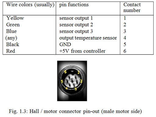
The question is, if you hooked up the wires incorrectly in the connector as shown in the picture below, would this cause the resistor to short?

He needs to figure out exactly why the resistor blew. Most likely he hooked up one of the wires up incorrectly, but I am not sure if hooking the wires up out of order would cause the resistor to blow.

Both times I blew the resistor it was because one of those wires shorted into the phase wires, due to damage where the wires exit the motor.

hall+motor+connections.png
 
Offroader said:
The question is, if you hooked up the wires incorrectly in the connector as shown in the picture below, would this cause the resistor to short?

He needs to figure out exactly why the resistor blew. Most likely he hooked up one of the wires up incorrectly, but I am not sure if hooking the wires up out of order would cause the resistor to blow.

Both times I blew the resistor it was because one of those wires shorted into the phase wires, due to damage where the wires exit the motor.

hall+motor+connections.png


Cheers mate, i have too asked him to fully check that his hall wires are soldered to the correct pins, it seems like the most likely 'human error' cause. I think he did mention to me that his hall colours were something like yellow,green and WHITE so it maybe that his hall wires do not have the USUAL configuration. This is a quote from him...
"I think my hall has problem
First step I check voltage from out from controller. I got -0.10V NOT 5V. I think I started to worry
I checked also from Black wire to yellow wire I got -0.10V, black to green I got +0.10V, then black to white I got +0.13"

But i think he said he had a QS motor? Surely they have the yellow,green and blue?.
 
BCTECH - First just to settle your mind and clear an obvious fault (human :) ), put the controller in 'SLESS'. If your still getting 'Halls!' it's likely dodgey Brake/Throttle/PAS wiring/soldering/issue.

Then do the H1-H2-....H6 check of the halls in the diag page, the one that you have an image posted. This will give you a rough indication that you have a Hall issue.

Do a proper Hall check 4.6v is around about the correct level, 4.64v seems to be the nominal. If your not getting a reading from one make sure you've rotated the wheel whilst checking :) ! If one still fails, dodgey hall, replace and check don't 'ass'ume :).

Due to the specific nature of the R113 fault and why it blows, once you've checked the functionality of the halls, with power off do a continuity check from every hall leg to all 3 power phase's and to the hub itself. Also, don't forget to Hall 'signal' to 'signal' as these should be isolated from each other. Signal is the middle pin on the hall, or if your going from the connector go between, yellow/green/blue (really should open your hub to check chaffing/shorting/loose connection etc...).

If you are sure that all possible chaffing/shorting between wires/hub/frame have been eliminated and the halls are serviceable, I'd honestly start looking at some of the info from our Russian counterparts. General jist, check the R113 SMD resistor resistance 2.2 Ohms, if this is the fault I'd suggest a careful hand at soldering and replacing the faulty SMD with a like for like 2R2.

There is further info knocking about about the range the SMD can be, something like 2.2 and 10 ohms (this is off memory so don't take as gospel).

If this has happened a couple of times I'd be very cheeky and suggest starting a build thread (or linking a current one) and doing a clear photo log of all your connections/soldering etc... inc hub disassembly, for two reasons A) it maybe something obvious to an observer and B) it'll ensure for yourself that you've checked and verified each process. Yes it's long and labour intensive, but it will likely point out the issue loud as day for yourself, others and Adaptto.
 
Offroader said:
The question is, if you hooked up the wires incorrectly in the connector as shown in the picture below, would this cause the resistor to short?

He needs to figure out exactly why the resistor blew. Most likely he hooked up one of the wires up incorrectly, but I am not sure if hooking the wires up out of order would cause the resistor to blow.

Both times I blew the resistor it was because one of those wires shorted into the phase wires, due to damage where the wires exit the motor.

hall+motor+connections.png

I am pretty sure I soldered the 6 wires correctly, I checked each one from the motor to the plug following the diagram of motor manual and the controller.
QS comes with 2 hall sensor plugs, both of them got me same result, so I assuming its the controller.
Unless both halls happened to be damaged at the same time for some reason.
what is the best way to double check halls at motor side?
I mean like checking if the sensor is dead or not without connecting to the controller
 
What are your hall wire colors, take a clear close up pic if you can.

You are using the 1st and secondary hall wires together if you say your colors are

Yellow, Green, & white.

Because White is part of the secondary hall wires.
Yellow and green are part of the primary hall wires.

I am going to say for sure you have mixed up your wires here. You should also take a resistance check between pin 4 & 5 and tell us what the ohms is to see if your temp gauge is hooked up correctly.

You will have to do a through check like ccmdr said above to figure out where you went wrong.

I think it should be standard procedure to rotate wheel wheel in the debug mode to check if the halls are working properly before autodetect.
 
I typed it wrong, it should be blue not white
so I got from the motor
1 Red 5V+
2 white Temp sensor
3. Black 5V-
4. yellow phase 1
5. Green phase 1
6. Blue phase 1

I then matched the wire color to the connector from the controller. Unless the 3 signal wires mixed up like yellow from controller should go to green from the motor. 5V red and black is crystal clear that I should not have mixed up. ok I will do the resistance check if it can help to find out more.
So now if I don't get 5V coming out from the controller hall connector, that's means I have a blown resistor? and will need to replace for sure?


Offroader said:
What are your hall wire colors, take a clear close up pic if you can.

You are using the 1st and secondary hall wires together if you say your colors are

Yellow, Green, & white.

Because White is part of the secondary hall wires.
Yellow and green are part of the primary hall wires.

I am going to say for sure you have mixed up your wires here. You should also take a resistance check between pin 4 & 5 and tell us what the ohms is to see if your temp gauge is hooked up correctly.

You will have to do a through check like ccmdr said above to figure out where you went wrong.

I think it should be standard procedure to rotate wheel wheel in the debug mode to check if the halls are working properly before autodetect.
 
BCTECH, I'll post the link here if anyone else may need the link for the 3.9 ohm SMD resistor that causes the halls error.

This is the one I used, and should be exact match to the one on there. Make sure to buy at least 10 of them, because you will lose them very easily while handling them and they are very cheap.

https://www.digikey.com/product-detail/en/samsung-electro-mechanics-america-inc/RC1608J3R9CS/1276-5004-1-ND/3967976
 
BCTECH said:
QS comes with 2 hall sensor plugs, both of them got me same result, so I assuming its the controller.

the QS hall sensor signal wires are duplicates, but the +5 and ground wires are actually paralleled for both sets of halls inside the motor.... if its like mine :wink:
 
Guys - for future reference there has been a couple of different pin-outs used over the past couple years for the throttle connector at the display end. If you use the throttle cable that came with the display - no problem. If you mix and match displays and throttle cables you may run into all sorts of issues. The guy that sent back his display earlier probably did so for no reason.

Make sure you keep the display and wiring provided together or be prepared to re terminate at the throttle connection to suit each display.
 
I have a Mini-E and a QS205.

The pinout of the QS hall connectors appears to be (looking at the pins of the motor side) ((+,T,-),(H1,H2,H3)).

There are two redundant sets of sensors and connectors, and one supplied female connector. It had some goop installed over the end that the wires come out, and I expected to find the female pins inside, ready to be terminated to my Adaptto cable, but there was nothing. Are we meant to get these pins with the motor, or are they a commodity item?

Crossposting to the Adaptto thread as I am also wondering about putting a small resistor in series with the hall power supply that can preferentially blow before R113, which is supposedly 2.2 Ohms. I have seen it reported that R113 can be replaced with 2-10 Ohms, does this mean I can add up to 8 Ohms for protection and have good operation of the halls? Anyone know what SMD size R113 is (I want to make sure the additional resistor is small enough to blow first)?
 
jmz said:
There are two redundant sets of sensors and connectors, and one supplied female connector. It had some goop installed over the end that the wires come out, and I expected to find the female pins inside, ready to be terminated to my Adaptto cable, but there was nothing. Are we meant to get these pins with the motor, or are they a commodity item?

i got 2 sets of female pins and 2 female plugs in a small snap seal bag with my qs 205, but prefer to use the adaptto halls plug as its more compact.
RTL
 
ridethelightning said:
jmz said:
There are two redundant sets of sensors and connectors, and one supplied female connector. It had some goop installed over the end that the wires come out, and I expected to find the female pins inside, ready to be terminated to my Adaptto cable, but there was nothing. Are we meant to get these pins with the motor, or are they a commodity item?

i got 2 sets of female pins and 2 female plugs in a small snap seal bag with my qs 205, but prefer to use the adaptto halls plug as its more compact.
RTL

I did find an empty plastic bag (and a machined disc brake spacer) in my QS box, hmm!
 
Allex said:
For those who have problems with saving throttle curves, Adaptto are working on this and will release new firmware shortly!


Dear friends,

We've released the new firmware which is already available on the web-site.
-The problem with saving throttle/brake limits is solved.
-Fixed the bug which caused blinking display once switching on the controller with high-voltage battery
-Eliminated custom logo on loading screen (appeared in some cases).

Please download here: http://adaptto.com/Support/

Firmwares with passwords for switching between power profiles are available via email request as usual.

If you'll find any new bugs in these firmwares please contact us via techsupport@adaptto.com with description!

Best regards,
 
Ohbse said:
Guys - for future reference there has been a couple of different pin-outs used over the past couple years for the throttle connector at the display end. If you use the throttle cable that came with the display - no problem. If you mix and match displays and throttle cables you may run into all sorts of issues. The guy that sent back his display earlier probably did so for no reason.

Make sure you keep the display and wiring provided together or be prepared to re terminate at the throttle connection to suit each display.
Thanks for the heads up
Why would they do that?
 
Back
Top