Adaptto Mini-E/Max-E Owner's Thread

I see that you managed to unscrew the halls connector. For those who are wondreing how:

First you need to leave the halls connector that is on the motor side attached to the halls conenctor on the controller.
Second, release the small cap that holds the cable
Third, unscrew the middle body while holding the motor connector(see 1), you may apply a bit of force there as most of them are secured with some varnish.
 
so looks like iv absolutely managed to frack this one! :shock: note the vapourise leg on the fet there.

the caps look ok, and the other circutry looks like it just has a little fallout powdered on it,so hopefully i should be able to replace the fet and trace to get it going again( i have a feeling it will be a little harder than that..... and probably end up sending it off for repair.
 

Attachments

  • PICT0018.JPG
    PICT0018.JPG
    59.8 KB · Views: 2,904
  • PICT0016.JPG
    PICT0016.JPG
    59.9 KB · Views: 2,904
ridethelightning said:
so its been a hard day.

after voiding the warranty on my spare new mini-e :p 
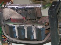
i found the halls error 1 problem caused by a hall wire in the controller that was not connected /soldered properly.

after fixing that, i went for a ride but only got acouple kms when i got PROTECTION on the screen. i tried auto detect and now get "halls error 2".

the r113 resistor seems to be ok at 4.8 ohms, so it might be something else

hall supply reads 4.5v.

i forgot to shrink the hall wires on the motor side plug, so its very likely that the 5v shorted there :| , the controller is now in lockdown protection mode, and i cant even reset it.

Hey man, i would recommand to AVOID puting any unprotected electronic device on a NON ESD plastic like that! that plastic cover you use is EXTREME electrostatic generator for small semiconductor electronic parts!!!

Dont forget that ESD ( Electro Static Discharge) often not dammage immediatly your electronics, but problem might appear later!!

Better use Glass surface or wood that are less ESD dangerous for electronic but i would avoid any plastic or synthetic or carpet :wink:

Doc
 
Hi guys, I'm 20 miles into my Max E ownership.. And all is good, it's brilliant, so configurable and the bms / coil charging is a dream..

2 quick question tho!

1. With lipo I have the max cell charge at 4.1, what would you recommend the balancing v to be set at? I got at the same 4.1 at the mo, I guess 4.05v would be better for it to kick in time???

2. I have a very faint clunk/jolt when applying and releasing the throttle when "feathering it" around cruise?

The Manuel does mention stuff about active engine braking (which is not switched on) involved with a jolt.. I disabled regen and it's the same....?? Any ideas??

on a side note, Ive tried the regen braking via a switch and on the smooth option.. All good there.

Thanks
Jon
 
Could really use some help setting up regen with wuxing thumb throttle!
Am I correct to wire it in parallel to my magura for the +5v and GND wires or do they need seperate power supplies?
The magura works fine in the current setup but when I switched the thumb throttle in and wired it up the same as the magura I got no response. Could just be a setting I havent found but I am not sure how to set this up.
Any help would be appreciated
 
hey man!

yeah its a bit confusing..

the same +5v and gnd wires for the magura are paralelled to the brake throttle.

only the wiper wire for brake(white from display)

and wiper for magura(blue?) are separate.

be careful. i have got WOT signal while i was wiring up my throttles together like that, i think cause the gnd was cut to the magura at some stage.

make sure you are in throttle lilmits/brake limits while wiring it up.

try wiring the brake up first by itsef, get it working, then the throttle by itself, before combining the gnd and 5+ , to help eliminate issues :wink:
 
Jonboy said:
Hi guys, I'm 20 miles into my Max E ownership.. And all is good, it's brilliant, so configurable and the bms / coil charging is a dream..

2 quick question tho!

1. With lipo I have the max cell charge at 4.1, what would you recommend the balancing v to be set at? I got at the same 4.1 at the mo, I guess 4.05v would be better for it to kick in time???

2. I have a very faint clunk/jolt when applying and releasing the throttle when "feathering it" around cruise?

The Manuel does mention stuff about active engine braking (which is not switched on) involved with a jolt.. I disabled regen and it's the same....?? Any ideas??

on a side note, Ive tried the regen braking via a switch and on the smooth option.. All good there.

Thanks
Jon

are you using a hub motor? jolt is likely due to the axle shifting in whatever torque arm your using. even the drag from the motor may be enough to make it move...
 
just setting up the bms and have a couple questions i cant find answers too...

1.
on adaptto site, it shows a 20s pack requireing 6 boards? shouldn't the 'top' 4s pack just be wired to the 5th board, and the 6th and 7th are redundant?
BMS-wiring-scheme.jpg


2.
if I split off the 5th board (for example) - is it possible to still use it if I connect up the 3 terminals via wire? ie can I position the 5th board separate to the main BMS board?

cheers all
SC
 
sn0wchyld said:
just setting up the bms and have a couple questions i cant find answers too...

1.
on adaptto site, it shows a 20s pack requireing 6 boards? shouldn't the 'top' 4s pack just be wired to the 5th board, and the 6th and 7th are redundant?


2.
if I split off the 5th board (for example) - is it possible to still use it if I connect up the 3 terminals via wire? ie can I position the 5th board separate to the main BMS board?

cheers all
SC

yes. you can.
 
Hey guys anyone in Australia have a spare adaptto screen? I've just smashed mine when my bike fell over and now all it does is just flash the backlight and the bike does not go, I'm in Perth so the closer the better, thanks, on a side note does anyone know the way to bypass the screen while I'm waiting for a new one?
 
ridethelightning said:
sn0wchyld said:
just setting up the bms and have a couple questions i cant find answers too...

1.
on adaptto site, it shows a 20s pack requireing 6 boards? shouldn't the 'top' 4s pack just be wired to the 5th board, and the 6th and 7th are redundant?


2.
if I split off the 5th board (for example) - is it possible to still use it if I connect up the 3 terminals via wire? ie can I position the 5th board separate to the main BMS board?

cheers all
SC

yes. you can.

any clues on the 20th cell being on the 6th board?
 
ridethelightning said:
hey man!

yeah its a bit confusing..

the same +5v and gnd wires for the magura are paralelled to the brake throttle.

only the wiper wire for brake(white from display)

and wiper for magura(blue?) are separate.

be careful. i have got WOT signal while i was wiring up my throttles together like that, i think cause the gnd was cut to the magura at some stage.

make sure you are in throttle lilmits/brake limits while wiring it up.

try wiring the brake up first by itsef, get it working, then the throttle by itself, before combining the gnd and 5+ , to help eliminate issues :wink:

Thanks for the help! I undid all of my connections and wired in just the regen throttle, giving a signal on the screen! as soon as I then wire the magura in parallel with it the magura works fine but no signal from the regen throttle. I have fiddled around with it enough to know that the regen will not work currently with the magura wired in parallel. To make it clearer, I can wire both throttles in parallel, then use the magura to spin up the rear wheel. If I squeeze the regen throttle now there is no response, but if I then disconnect my magura from the GND so it is no longer in parallel with the wuxing throttle, the regen will then work perfectly. I deosnt seem like the throttle like sharing the same power source, but I am unsure why. Any help or pictures from people who have variable regen set up would be appreciated.
Thanks
 
sn0wchyld said:
ridethelightning said:
sn0wchyld said:
just setting up the bms and have a couple questions i cant find answers too...

1.
on adaptto site, it shows a 20s pack requireing 6 boards? shouldn't the 'top' 4s pack just be wired to the 5th board, and the 6th and 7th are redundant?


2.
if I split off the 5th board (for example) - is it possible to still use it if I connect up the 3 terminals via wire? ie can I position the 5th board separate to the main BMS board?

cheers all
SC

yes. you can.

any clues on the 20th cell being on the 6th board?

In the example above you have a 21s pack, you cannot have one cell on the board so this is why they moved cell 20 and 21 to number 6

Seven said:
Hey guys anyone in Australia have a spare adaptto screen? I've just smashed mine when my bike fell over and now all it does is just flash the backlight and the bike does not go, I'm in Perth so the closer the better, thanks, on a side note does anyone know the way to bypass the screen while I'm waiting for a new one?

New screen is 151USD shipped, delivery time <5 days, will send you a PM.
 
Another listing for those in the states.

This one is a little cheaper too. It says IP68 so hopefully there isn't extra O-ring thickness or something that prevents plugging in to the Adaptto end...

Cowardlyduck said:
striker54 said:
Cowardlyduck said:
So I don't have to change the halls plug (again), does anyone know what the name of the 7 pin halls connector is?

Cheers

Search for "ip67 7pin"
Thanks!
This one looks to be a match.
http://www.ebay.com.au/itm/IP67-IP6...ric-Cable-Wire-Connector-M14-7-/291050868476?
ux_a13103100ux0050_ux_c.jpg

Does that look right to others also?

Cheers
 
Anyone have any positive/negative feedback on this connector? I don't really like them...no problems or anything, just a personal opinion...I find them clunky and awkward.
Am I missing something? Are there any positives to these that I'm missing?
 
yeah they are a bit clunky.

they are waterproof and durable though.

have you found any better that are more compact that do the same job?
Wheazel said:
Is it normal that the set speedlimit in the power profiles never is reached?
Its consistent for me that the actual speed ends up a few km/h lower than the set limit.

For example, I have a 28km/h limit in ecomode. This makes the bike go 25-26km/h on the flat.

i think its normal. i think its to do with the way the system limits power when it approaches the set speed. i always set mine higher to get the speed i want.
 
Most of the builds are now with big, spacious frames, so you can actually have all connectors inside nowadays.
Pehaps something smaller, like these:
http://www.aliexpress.com/item/LEMO-connectors-FGG-PHG-0B-2pin-3pin-4pin-5pin-6pin-7pin-8pin-Male-female-power-connectors/32359806931.html
 
they look like really nice connectors allex, but they dont look much more compact than the llt ones. they are most likely heavier too.
they might be nice for other applications than connecting to controller.
 
Anyone have any ideas as to what setting would cause the controller to heat up very fast? I am running 12kw peaks into a high speed wind cromotor but the bikes fairly light and even running around at <60km/h its getting hot where the cro is sticking to only 40c degrees. I had a stock Stealthbomber hub on there before which was the opposite where the hub was getting really hot and the controller was sitting at a nice temp of around 39c. The controller is mounted inside the frame but it is thermally connected to the frame so its got alot of area to disapate heat even if it is not air cooled.

Currently i have
Angle corr -5.1
PWR timing 1.6
OVS at 3
IND timing 430

Derek
 
Dear Friends,

We've started a new thread to discuss your suggestions for the future functions to be added for our controllers.
Please share your thoughts here: viewtopic.php?f=2&t=71956

Best regards
 
Adaptto E-Drives Lab said:
Dear Friends,

We've started a new thread to discuss your suggestions for the future functions to be added for our controllers.
Please share your thoughts here: viewtopic.php?f=2&t=71956

Best regards

Thank you!!
 
Bluefang said:
Anyone have any ideas as to what setting would cause the controller to heat up very fast? I am running 12kw peaks into a high speed wind cromotor but the bikes fairly light and even running around at <60km/h its getting hot where the cro is sticking to only 40c degrees. I had a stock Stealthbomber hub on there before which was the opposite where the hub was getting really hot and the controller was sitting at a nice temp of around 39c. The controller is mounted inside the frame but it is thermally connected to the frame so its got alot of area to disapate heat even if it is not air cooled.

Currently i have
Angle corr -5.1
PWR timing 1.6
OVS at 3
IND timing 430

Derek

id try doing auto detect 5-6 times in a row first
with ovs set to 0

after that, tune the settings like angle correction and ind timiming manually.

if you changed your battery voltage after last autodetect, that will also cause heat from bad tuning.
12kw peaks is a fair old whack and id be suspecting the the controller is in need of fresh air :D
especially with a fast wind.


have you got the correct temp sensor settings? does the controller actually feel hot?
 
Back
Top