Animalector's Ebike Builds

Ok, now that I see the video of you starting up the CA V3 it looks like an under voltage condition to me (I've seen this behavior while bench testing at low voltage). Do you have any pre charge resistors inline or is the ignition wire going straight to the battery? The CA is powered directly by the ignition wire.
 
No pre-charge resistance (hence the big spark), though I pushed the ignition wire into the terminal when testing yesterday, so it could be a high resistance contact on the spade.. or the spade crimp could be a bit nasty. The behaviour of the backlight might suggest low supply conditions. I might not stress just yet. perhaps once I solder everything in permanently it will sort the issue out. (cut that spade off)

otherwise I will look into the Firmware suggestion. I Don't have a programmer for the CA, but should be getting one from a mate once he buys his...

Thanks for looking at it, and offering your suggestions
Andy
 
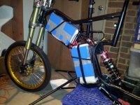
spent the afternoon packing the batteries into the frame. I've got all contact surfaces with foam sandwiched between the frame and the pack and it's all quite tight, I've added Velcro straps to hold it all in,
20131209_213639 (Custom).jpg

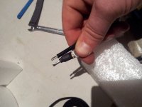
Plus here's a comparison of the phase wires and some 12ga wire I had lying around. I am pretty pleased. Any ideas what sort of peaks these phase wires will handle?? THey measure 2.5mm diameter
20131209_213310 (Custom).jpg

Andy
 
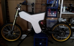
Well not much work tonight. Really waiting on the connectors and breaker and rear brakes to get much more done. Although I did tidy up the wires and Mount the controller connect the phase and Hall wires then trial fit the covers it is going to look so good when it's done. Although it looksa little too "front heavy" like all the action is at the front half of the bike. I think if I get a rear mud guard it will even the looks out a bit.
2013-12-10 21.58.05.png
Oh also I'm thinking about fitting some Window rubber to semi seal the covers onto the frame. I sawa post on here of someone else who has done that. Might have been Alan B..
Anyway. ...
 
How tall are you? That seat post is WAY up compared to mine which is only about 3-4cm out of the seat tube and I'm 183cm tall. My bike is quite tall.

Could be do to component choice of my rear shock/fork since we are both using 19" MC wheels, funny how the Greyborg makes 19" MC/wheel tire combos look small.

Have you had any comments yet on how the bike looks? Mine always gets attention when I take it for a short ride and I often get comments from people and others on bicycles of all ages on how "cool" it looks. I never knew so many people were into bicycles.
 
182cm I rode it 14km the other day and got sore knees from being cramped. I didn't have enough leg stretch. Plus I actually like to pedal. I haven't ridden it around anywhere yet except for on the street outside my house and not yet under power . But yesterday I had little ride around and the seat position felt much more comfortable. If I end up getting a yasusu shock they are 260mm eye to eye so that will lower the seat workout affecting leg .
length.
Anyways even on that first ride the other day no batts no side covers people were staring. And I found a few guys checking it out at the gym where the squash courts are so I had chat with them. Plus the guys at work keep asking to check out the latest pics of the build and can't wait for me to ride it in
 
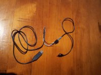
Wired up this programming adapter for the CAV3. Just have to hold down the button while programming but that's pretty easy to do. Worked well. Now if only the CAV3 would actually turn on...

20131212_203344 (Custom).jpg

Andy
 
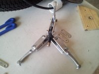
Ok so I finally got a tool to get the side covers off.. That was a mission. I bought the one which I thought was "big enough" and at max setting it could only get two of the three prongs over the lip of the side cover. So out comes the hacksaw, and chop up 6 longer linkages, drill some holes and tada.. hey presto.. modified tool (I'll attach some photos of my ghetto tool later)

Anyway I accidentally cut into the insulation of the main cable while removing the side cover. They have a plastic ring to hold the cable in and when the side cover was lifted, that cut into the insulation. I caught it before it got into any cables, so it should be fine.

The reason I opened the motor was to install a temp sensor (LM335) there's no chance I will squeeze another cable through the the hole, so I am thinking about using the +5V and GND for the backup set of halls. then paralleling the +5 and GND from the first set to the second set. or maybe just leave them disconected - suggestions? I can always open the motor if I lose a set of halls. What is the likelihood of blowing a set of halls that aren't being used but have +5V applied to them.. ???? what blows halls?

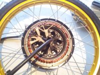
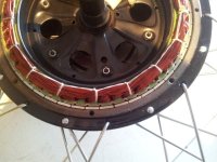
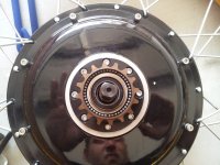
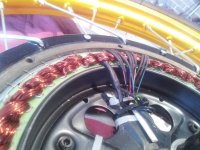
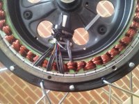
So here's some pics of the guts. Like Zombiess motor, there's a slightly larger gap between one set of magnets though I think it's not as big as Zombiess.

QN... Is it normal for the motor to 'attract' to one point with one side cover removed? I think that when the cover is re-installed and the bolts tightened it will 'center' the motor again, correct? pretty sure it will be fine.. and that this is normal.

ok ok pics.
20131214_194636 (Custom).jpg
20131214_194709 (Custom).jpg

Andy
 
Animalector said:
Wired up this programming adapter for the CAV3. Just have to hold down the button while programming but that's pretty easy to do. Worked well. Now if only the CAV3 would actually turn on...
Andy

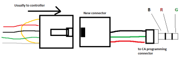
You got a pin-out for that mod, need to do the same thing to mine.
 
so I am thinking about using the +5V and GND for the backup set of halls. then paralleling the +5 and GND from the first set to the second set

That's what I meant by this... It's a LM335 so only 2 wires. I am not sure though if i power the second set always will there be issues (could I blow my spares?)

Come to think of it. I could parallel the GND's, for all 6 halls plus the LM335, then use the freed up GND wire for the LM335 signal.. that will work, then I still leave my spare set of halls unpowered. I wonder if paralleling the GND for the LM335 and the halls will create interference on the Temp sensor signal, I think the GND's are just common in the CA anyway. I'll measure.

Jolly good. Here's how I wired up the programmer.. not very 'techie' but you'll figure it out.
Programming connector.png

Andy
 
The CLAW!!!!!
20131215_104115 (Custom).jpg

This catches so I might replace it.
THe other freewheel I have isn't much better. might buy a shimano or something.
20131215_105632 (Custom).jpg

Another pic of the guts, removed this side so I Can get at the wires and wire in the temp sensor.


Andy
 
dammit.. I just read the CA manual ...
Ground Reference: It is recommended that the thermistor ground be tied to the provided CA PCB Gnd pad
and not be shared with other devices. This policy minimizes unwanted voltage offsets between the CA and
thermistor grounds which will affect the measured sensor voltage

well I might have to pull the back side cover off and figure out how to get another wire down there. I don't want to permanently power both sets of halls. perhaps this will be the only way to get two wires into the motor? Job for tomorrow.

Bought a shimano freewheel too.. the other spare I had felt just as notchy as the original.

There's a pretty convenient loop of wire that happens to snugly fit the LM335
20131215_190443 (Custom).jpg
20131215_192542 (Custom).jpg
 
Well, wired up and tested the temp sensor. It was not immediately obvious what the settings were for. I had to read the wiki for the ca. And then the grinn website. Anyways long story short. If anyone has a lm335 the 0 offset volts is 2.63 which from the datasheet is 2.98 at 25º and 10mV per degree. So minus 250mV.
The display is now reading 23 degrees which fora Melbourne summer night is probably about spot on
 
Animalector said:
It's a LM335 so only 2 wires. I am not sure though if i power the second set always will there be issues
Unless it's a resistor type thermistor (which the LM's are not) it will have 3 legs, -ve +ve and signal. Same as a hall sensor. It'd totally pinch + and -5v from the existing hall wires and just run a single new wire or borrow one from the spare set of halls. I've not had a hall blow on a motor with dual sets of halls but I imagine you can't mix and match halls so if one set goes you'd need to switch to the whole new set (ie for example not just use the spare yellow one)

Nice work with the build so far, you must be itching to get out for a full powered thrash (over the xmas holidays?)
 
This LM335 was pre-wired and heatshrunk with only two pins, so the V(adj) pin is probably not used. it doesn't need a +5 supply like the LM35, it is a zener style, and relies on the pull up inside the CA.. Anyway. Motor side covers are back on, and I'll give it a test run to see how it performs, if it's noisy or causes feedback issues I'll open the motor back up and probably re-wire the whole thing. new phases etc.
but I imagine you can't mix and match halls
I actually think you "may" be able to. The halls are physically mounted on the same "phase / coil" but on the other side of the motor, and wired colour for colour, so I think they could be interchangeable. I've not thought long and hard about this but gut feeling is it would work. I could always test....

I am very much waiting for a full powered thrash.. but am holding off wiring the battery in until I get the anti-spark connectors and the 100A breaker. The reason is the battery and controller wires are very short and the more I add / remove connectors the shorter they get. and I don't want too many soldered extensions in the system.

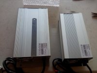
On the plus side i got my chargers today
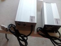
20131217_174153 (Custom).jpg
20131217_174224 (Custom).jpg
I'll have to change the connectors on the bigg'un Also, powering up and testing only gave 74.5V on the small charger, the big on had 0V.. but I figure it's a "output on detect" type circuit, so until a battery is plugged in, can't tell.

Andy
 
Quick Question,

Without learning all there is to know about motor technology, and because I am somewhat lazy..err I mean, somewhat busy with other things....

Can someone tell me how many poles are in this motor? And how I can tell? there are 51 magnets. (I am pretty sure of this I counted them twice) well at least I think I remember counting 51 twice.

Thanks
Andy
 
I just re counted 46 magnets. Not 51 dunno where I pulled that from. Now it all makes complete sense. The count of 51 was throwing me. And I counted twice? Perhaps one to many scotches that night
Thanks guys
Andy
 
that bike looks like a blast to ride. Loving the battery setup. whats your max voltage hot off the charger?
 
That's a great question. Considering I only got my chargers yesterday I haven't actually charged them yet but they will be 75 ish volts. Since they are 18s NCM lipo.

Also I am sure hoping it is a blast to ride i haven't ridden it under power yet. Hopefully I get the connectors and circuit breaker before Friday otherwise won't get anything done till after new years.
 
Well it looks like i will have to wait until after new years to finish the borg. My connectors haven't arrived yet and I am just about to board a plane for Cairns in sunny far North Queensland.
Merry Christmas to all.
Andy
 
Back
Top