casainho
10 GW
- Joined
- Feb 14, 2011
- Messages
- 6,058
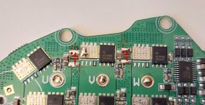
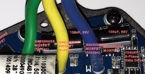
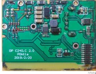
You are going well!!CiDi said:casainho said:Please draw colors on the traces, so we can understand where they go. Change the color when there is another component on the path, like that resistors. Measure the values of each that resistors, maybe you can number them and say here their value. For now, let's focus on the Vcc pin and on/off pin.
Are those components capacitors or resistors?
That tiny black like between orange line and red, should be all resistors. Please measure them. If they were capacitors, you would probably measure a very high resistance like 1Mohms or even higher. For instance that resistor between the yellow and GND, I expect be be a low value, maybe something lower than 500ohms - that one is in series with GND signal, it is probably just for protection against wrong cable connection or such.
That bigger ones near the red line, are probably diodes. You need to measure them with the multimeter on the specific option to measure didoes - on didoes the current just can flow in one direction and we need to know where is the negative, cathode pin, that usually has a line on on the package.
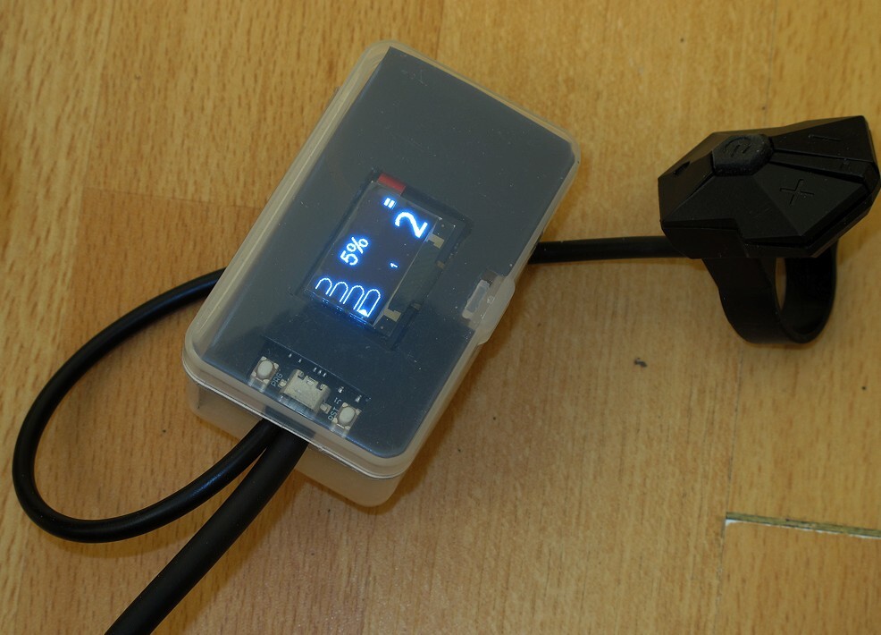
What is the 0/1 pin on the keypad? is it the on/off button? -- my expectation is that buttons only short each pin to the GND, you can check with multimiter also.
If 0/1 is on/off button, than we already can see Vcc will have a connection to on/off button trough some resistors.
That 2 diodes, it is very important to understant the signals there. I think there are resistors probably to make a pull up (or pull down) - you can check it while not pressing the keypad buttons, if that buttons are 3.3V or 0 volts. We can clearly see the traces then going to the connector on the bottom right, that connects to the other board where is the microcontroller.


")