Hi,
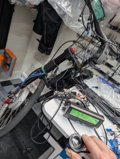
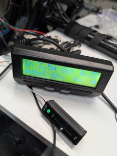
I have access to a BionX kit with a G2 Console and a remote throttle switch, all fitted to a handbike. The owner of the bike is physically impaired and therefore unable to press the button while riding although this would really help him riding more easily and independently.
I'm trying to build a switch for him that mimics the behavior of the BionX throttle.
Sadly, BionX didn't even care to respond when I asked them for help with this project.
What I have found out so far:
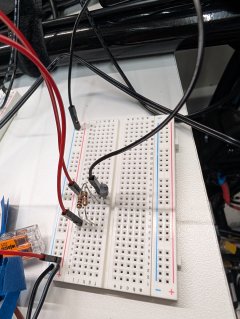
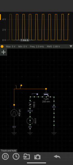
There's a hall effect sensor and a magnet that generate the signal (looks like a kind of PWM) to the controller. The "low" part of the signal gets stretched out the more the throttle is pressed. My best guess is, that the controller measures the "low" time when the switch is not pressed and when it is fully pressed and derives a relative position of the switch from that (for example, signal goes low periodically for 2.5ms equals not pressed, signal goes low periodically for 4ms equals halfway pressed).
The + and - buttons add another low level shortly after the "throttle pattern" when pressed.
My plan is to use a microcontroller to switch the signal according to this pattern.
My questions:
I searched this and other forums but didn't find anything similar. Has anyone done something like this before?
Does anyone know more about those throttles and can help me understand the electrical characteristics of them?
Thanks,
Tobias
I have access to a BionX kit with a G2 Console and a remote throttle switch, all fitted to a handbike. The owner of the bike is physically impaired and therefore unable to press the button while riding although this would really help him riding more easily and independently.
I'm trying to build a switch for him that mimics the behavior of the BionX throttle.
Sadly, BionX didn't even care to respond when I asked them for help with this project.
What I have found out so far:
There's a hall effect sensor and a magnet that generate the signal (looks like a kind of PWM) to the controller. The "low" part of the signal gets stretched out the more the throttle is pressed. My best guess is, that the controller measures the "low" time when the switch is not pressed and when it is fully pressed and derives a relative position of the switch from that (for example, signal goes low periodically for 2.5ms equals not pressed, signal goes low periodically for 4ms equals halfway pressed).
The + and - buttons add another low level shortly after the "throttle pattern" when pressed.
My plan is to use a microcontroller to switch the signal according to this pattern.
My questions:
I searched this and other forums but didn't find anything similar. Has anyone done something like this before?
Does anyone know more about those throttles and can help me understand the electrical characteristics of them?
Thanks,
Tobias