Brushed hub motor: 1 set of brushes verses 2 sets?

goinmobile

100 mW
Joined
Apr 23, 2012
Messages
48
Will an added set of brushes spread reduce the heat issues of these motors?

My problem is overheating, causing spring collapse, brush wire burning & the de-soldering is common for all. Controller failure may be the real issue as the bike has ran for 1 year & less, per controller. On failure, perhaps direct battery voltage hits the motor?

My understanding is the motor winding resistance will limit the current. A controller can limit current further. If that is not correct please post with reference, not opinion please.

The motor photo reference is in a Monkeychops thread in Dec, 2011, posting #104. Topic heading "Re: 10 year old lead acid 36v e-bike needing an upgrade", Thur, Dec 29,2011 8:14am. 4 others have also posted on this motor, a Strong GT-S210 (gts210, gts-210, gts2-10).

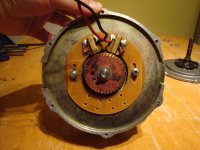
Monkeychops photos show the brush plate. It has holes for a second set of brushes. The angles are not at 90" that I see in other 4 brush motors. Is it relevant?

This motor's brushes are small, a surface area of 4.2mm X 4.9mm. Will using 2 sets reduce the current per brush set, by half?

Can 2 sets increase the power (not intended)?

Will brushes last longer, or not because RPM friction wear has not changed?

Thank you for considering my questions.
 
When I opened up a Heinzmann brushed hub motor, I noticed right away that it had dual brushes. I have no idea how it worked electronicly, if they ran two seperate windings, or was a paralell connection to the same winding.

Seemed like a cool idea. But the motor had melted, so for me it wasn't enough improvement to keep the motor cool climbing hills.
 
Hope you don't mind me adding these pics, for the Brains to consider your query. :wink:
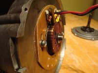
I, like you considered sacrificing one motors brush holder to create a double motor. There is even room to get the extra wire out.
Curious to see you accomplish this. Good luck :wink:
1 set Brush, 2 possible.JPG
1 set Brush, 2 possible. side.JPG
 
On this motor, the commutator plates have 0 resistance between any 2 plates, does not matter which plates, side by side, or opposite, or random. I expected a pattern before the test, conductive & non-conductive. Logic has flown out the window.

Does this indicate a short? Can carbon powder between the plates give the conductive reading on my ohm meter? There is no continuity between a commutator plate & the motor shaft. Is this conduction only so to a meter, minute conduction between plates, were as 99.9% of the operating current travels as intended in operation?

Some background on this motor. 36v, 500w maximum, 200w nominal, 230rpm at the wheel. I've read the motor is called a pancake. The windings are not visible, it may be loops like a Heinzmann instead of windings as it's very thin. I am using JC-116 36v-500w controllers, I don't notice a speed difference from the factory controller rated at 500w & the replacements.

This mystery deepens Dogman.

Thanks for posting your photos here Brentis, that looks just like one of my newest motors! So your wife should have less grease on her clothes now you have emptied the closet a bit, haha. Co-hab closet living means the frames are hung & the wheels tucked below the hem lines.
 
If you are reading a short across *all* comm segments to all other comm segments, there's something wrong. It shoudl only read between pairs that are at the same spacing as the brushes. Everything else should read open.


Adding more brushes in contact with the *same* comm segment pair will help reduce the current load on each brush, if you have enough segment length to work with, and space to put the brushholders in. This is not uncommon practice in large brushed motors (like forklift motors), in original design.


Adding a whole new set of brushes in contact with a different pair of comm segments can change the way the motor works, and might cause problems depending on where you choose to do that vs how the magnets are laid out vs how the motor is wound, etc. You can experiment with it to see, but my guess is that if it works at all, you'd need them to be "90 degrees" off from the existing pair. I am not sure it will work, though, because it will be energizing a different coil that at that time is 90 degrees off from the magnets it needs to be pushing/pulling against.


There are motors called 4-pole motors that already have a second brush pair, but they also have 4 magnets rather than two, and the windings are different, too. These usually spin at half the speed of a 2-pole motor (a single brush pair), but at twice the torque (and current draw). It might be possible to convert a 2-pole to a 4-pole, but it will not be all that easy and may not be worth the effort.
 
Thanks for your help AW.

I'll retest for continuity across the commutator plates. I may have misaligned as the brushes are out. Test another one also, with brushes.

The dual brush holder pattern in the photo may be a standard sized part, used on other motors too.

Its Chinese generic, you can smell the commie stink when you crack the cases. If they would sell replacement parts in vendor quantities, I bet the smell would change too.

Busy today, by tomorrow for sure.
 
commie stink?

everyone else thinks it is slave labor sweat smelling it up.

did you not hear that deng has said that 'to be rich is glorious'?

those brushes will not handle more than about 2A imo.
 
You should get continuity across all commutator segments. Since each segment is attached to two coils, the wire just runs all the way around the entire motor. You should get SOME resistance on opposite sides of the comm, but most multimeters won't read low enough to recognize it as more than a short circuit.


If you double the brushes (it sounds like you have the holders inside), you will increase motor rpm/volt by 2x and halve resistance at the motor leads if we assume all brushes are equally spaced around the comm. If your controller can handle the lower resistance and is current limiting, the average amp density on the brushes will be cut in half. The second set of brushes has to be electrically parallel to the first, otherwise the motor couldn't run with just a single set. Like having a dual coil speaker that can be changed from 8 ohm to 4 ohm by tapping one coil or both in parallel.


You can guess at the pole count of the motor by measuring the angular brush separation in degrees. A motor can be run with 180 degree brushes if it is two pole. 90 degree brushes indicate 4 poles or greater multiple of 2. 60 degrees indicate 6 poles or greater multiple of 3. 45 degree brushes indicate 8 poles or greater multiple of 2. etc etc
 
amberwolf said:
If you are reading a short across *all* comm segments to all other comm segments, there's something wrong. It shoudl only read between pairs that are at the same spacing as the brushes. Everything else should read open.
This is not normal for any brushed armature I have seen, Having said that I have only tested a few EV brushed motors and 1000's of car/motorcycle starters..... AW are you realy sure of this???
 
No, I'm not. But that's how the few brushed motors I have unwound were wired--a single winding from one comm segment to the other one 180 degrees across from it. I also don't see how they could work to do what they do if they were wired such that all comm segments read a short, but I have been unimaginitive in prior such situations. :)

If I were over on DIY Electric Car forums I'd just ask Major; he seems to know *everything* about most kinds of motors (maybe all of them).
 
I retested, plus another motor, both the same. 38 commutator plates. Brushes are 45". I cannot see the magnets or windings.

Perhaps the brush position is set wrong, causing heating. I removed it to polish clean the commutator. You can see the variable in the photo. The brush width is slightly wider than a plate, but still has an air gap on ea

A close look shows that BOTH brushes can be on one plate ONLY for a short period of time OR adjusted so one brush contacts 2 plates & the other only contacts 1 plate.

Can that overlapping contact energize an apposing force resulting in the heat issues?

Cause of the stuttering too?
 
Ok, nevermind what I said; my memory is failing me. I happened to have one of the motors I'd taken apart but not unwound in a box I could get to while getting some other stuff out, and it looks rather like JRH describes. :?

The only part of what I said before that I *am* certain of is the bit about the brushes vs magnets vs 2-pole / 4-pole. I think.
 
Extra brushes is not the answer to this motors heating behavior. It's cause is brush position or it needs a smaller controller. Treating a symptom instead of the disease.

The substitute controller(s) are JC-116, cheap. The last one lasted a year, until I broke off the throttle awhile back. So mis-adjusted brushes does not kill them.They are rated at 500w, no nominal or peak power given. This replaced 200w nominal, 500w peak. I did not note an increase of speed, but not certain as I only tested for a mile, then replaced with new parts.

I described brush positions in my above post, forgot to complete the sentence on brush & commutator plates, the brushes can be set so each contacts one plate only at that segment of rotation. The next rotation segment contacts 2 plates. 19 times per revolution.

Thank you Johnrobholmes for the math reasoning, you likely experienced this brush issue also?

Amberwolf, I got an acct opened at DIY.

Brentis, I think I had commented on brush setting before in your thread. My memory of the brush holder had the screw slots rotating, correct purpose is in or out to set contact degrees.

Just to verify my thinking, what is the correct contact setting?
 
I've had some 4 brush motors before. If you run it on 2 brushes, it runs about the same, but obviously the brushes are taking twice the current.

The resistance between commutator segments is going to be typically less than one ohm, so unless you have a special meter, it will look like a short. This is normal.

If the brushes are overheating, adding a second set will definitely help. If the motor windings are overheating, adding more brushes won't help. Also, brush composition varies widely, so maybe they're using crappy brush material. Increasing the brush spring tension will help with heating also. If the springs are weak, there will be more arcing and heating on the commutator.

In the motor in the picture above, if the second set of brushes is installed, they would be connected in parallel with the existing set. The connecting wires would need to cross over (like an X).

If the brush plate is adjustable, you can tweak the motor timing. I like to adjust for minimum current draw at full throttle (wheel up). This will be pretty close to neutral. If you advance the timing, the motor will go faster, but the current will go way up and fry things or result in poor efficiency.
 
Fechter, Thanks for your help. You are correct on the meter, only reads to 1.0 ohm on the 3.5 K ohm setting. Reads to 0.001 volts too.
No decent amp meter yet.

Do I set the brushes to only contact 1 commutator plate for each brush? I don't think it's in/out adjustment range allows spanning to another plate that's not the intended current path. It does allow setting on one plate & the other brush contacting 2 plates.Will that cause heating by opposing forces? This tolerance can be observed in the first of Brentis's photos.

So adding brushes can work, I should install on a test motor for the ES proven knowledge wiki (?).

I think timing & spring tension are the real causes. I refurbished this motor last year, substituting a collapsed spring with a slightly larger diameter one, cutting its length. At that time I had thought of using 2 the same, but the length might cause faster brush wear from extra tension. Hence the 2 different size/tension, then observe on the next refurbishing. I'll check this right now & get back.

I have one auto electric shop in the next town, they rebuild. I can't buy brushes by size, only by part number, sucks. In person may work, but difficult, no car. Is there an internet source for quality & sizing? Canadian buyer.
 
it does sound like a spring tension or timing issue to me. Otherwise the motor is just getting ran too hard, which is a possibility.


I haven't had any experience with brushed hub motors. I just build brushed motors for a living and have done a lot of research on multipole design. You may be able to find a suitable brush from Helwig Carbon.


Don't worry about the brush overlap on the comm. The motor should have been designed properly in this regard. You could always thin the leading or trailing edge of the brush to reduce the commutation duration, but it is generally better to just reduce timing and keep the full brush face in order to avoid amp density increases in the brush.

Reduce the motor timing by moving the brushes in the same direction as the rotation. To find zero timing, move the brushes until the amp draw is lowest with no load. Then increase the timing just a bit to reduce arcing. I generally suggest a 10% increase of idle amp over zero timing for small RC motors.
 
JRH, I'm limited to eye adjustment, no tools to measure amps. I cannot adjust from outside, no access plate in the cover. So alignment will change slightly with cover & upper bearing in place.

I keep trying to explain the brush contact variables. Does one brush contacting one plate & the other brush contacting 2 plates have any meaning? Further rotation will have both brushes contacting 2 plates each, a normal rotation function. Its that moment of 2/1 contact I'm questioning.

My reasoning is the commutator conducts between plates, so the positive brush contacting 2 plates & the negative brush contacting 1 plate will complete 2 circuits (instead of the design intent of 1 circuit, at that moment of rotation). So this will fire the next rotation "field" too soon. Therefore opposing forces resulting in heat. True or false?
 
goinmobile said:
I keep trying to explain the brush contact variables. Does one brush contacting one plate & the other brush contacting 2 plates have any meaning? Further rotation will have both brushes contacting 2 plates each, a normal rotation function. Its that moment of 2/1 contact I'm questioning.


Don't worry about it. Contacting three or four segments on a multipole motor is not out of the ordinary. There are always two paths of current through a brushed motor. Like I said before, if you want to play around with commutation duration you can thin the brushes. It is very unlikely the motor was built with an oversaturating duration.


You are flying blind without an amp meter. You can get a cheap multimeter from about anywhere, without this tool you will never be able to figure out anything beyond a visual check.
 
Sorry I don't understand electronic terms, what a word or term implies. I got it now. Thank you for your patience John. And everyone else.
 
Back
Top