Crystalyte Controllers - Repair and Modification information

On the high power FETs, it's usually not a problem. It can REALLY screw up a sensitive op-amp circuit though. I scrape off the big chunks with a small screwdriver, then spray it with flux remover. Rubbing alcohol and an old toothbrush sort of works too.

The flux residue tends to become more conductive with humidity as it absorbs moisture from the air.
 
+++++++++ U P D A T E D FET SELECTION GUIDE +++++++

I updated the fet selection guide that Fechter did with some fets that are already integreated in crystalyte controller and some that Justin used to repair temporary like IRF3502, IRFZ48..etc

Doc :wink:
 

Attachments

  • FET_selection_guide UPDATED 27june2007 normal.xls
    25 KB · Views: 332
I've blown a controller, I don't know how i did it !
As soon as i connect the battery's the fuse blows so I opened it up and there are no visible signs of damage.
I have a dead short between the power leads
Testing ohms accross the fets gives the same readings on all (no shorts)
The gate resistors all read correct.

So what do i do next :?:

Any constructive help appreciated
 
If one of the capacitors shorted internally, it would effectively short out the power leads... Do the capacitors all look ok?

I'm not sure that we want to open up this thread with a troubleshooting discussion - maybe post up a new topic and then post up a summary into this thread when you get it working again?
 
I agree about the caps, you could also check for the voltage regulator transistor 13005 (a to-220 case) If i remember, it is directly connected to the V+ and is linked to a 2N5551 small transistor that could blow too.. often shorted I learned..... you could also check the 12V zenner under the big 3W resistor(that resistor absorm the voltage balance from V+ to go the 12V rail that supply many IC.

About my controller repair, repair I finally have one fonctionning!
Justin sent me 2 slightly blown 35A controller with some fets blown and iI repaired one with the two other using components. He had no one left to send me for the warranty, so he did his best to help me sending two controller for the components

I had a very great service from him.

-----Anyone have some IRFB4110 fets stock? i need 12 to upgrade!-----
 
I seen that if your controller blow and affect the 14V supply, this rail may blow many IC supplied by it.

The R46 (a 100ohms near the KA3526 IC) could blow too. in this case you will measure around 6-8kohms acros the leads

Doc
 
I HAVE INTERESTING DISCOVER TO SHARE WITH THOSE THAT HAVE A BLOWN CONTROLLER!!


I just got a used APC ups from my frined (the same that gaved me 122 18650 li-ion used cells.

I just look to see if some interestingfets could be found inside


S U R P R I Z E !!!


I found:

3x IR2101 low/high fet side driver!!! (cost: 2.69 each) and difficult to get

4x IRF3105 fet 110A 55V able to drive up to 40V a controller.

1 UC3525 PWM ic (cost 2.29$)

1 LM358 (cost 0.49$)

1 LM393 (cost 0.79$)

total found: 11.64$

Except for the IRF3205, ALL these component aree used in the 72V 35A start imediate controller!!

All those component CAN be used to check your blown controller and avoid you to wait for availlability of component for digikey, newark, E-sonic, fairchild...etc... you could just go to your loca computer repair shop to see if they have some broken UPS..


Mine is'nT blown (at least the output side...)
maybe is the thyristor on the input that have toke a too big AC voltage spike and blown..
Well.. i now have component to rebuild 3 controller.. lol


All these component came from a 1000W ups !!!!!


Doc
 
I've just ordered 120 IRF-4410PBF's from http://www.irf.com

These are the 100V / 75A Mosfets with really low (4.5mOhm) on resistance that will hopefully end my blown controller woes.

Not sure when they'll arrive, next week I hope.

If any Aussies want some let me know and I'll express post them to you. They'll work out at about A$5 each.

(thanks to Lowell for the suggestion and authors of the FET selection guide!)
 
I hope you mean 4110s.

By the way, how hot can the controller get while remaining stable? I'm using 96V (104.8V peak no-load) with the 35A controller with the 150V FETs, and it gets hot even after a fairly short and light ride -- I measured the inside temperature as being around 148 degrees Fahrenheit (outer casing was 128 degrees).
 
Does it not have a temp sensor/cuttout?
My 20A72v controller does, and cuts out at around 75C or so (external temp)
 
thanks CGame, 4110, not 4410s.
 
Hello everybody, I just discovered this forum
and maybe you can help me. I have a Crystalyte 408 motor with 48V 20A controller. I want to try it with 2 DeWalt packs wired in series to make 66V. Do you think it is possible to upgrade the controller just changing the MOSFET's?
thanks
 
Yes ^^


And, Might I add, Three Cheers for the Fechter!! May you become a deity amoungst sick controllers everywhere! (you saved mine from an early grave!)
 
itron said:
Hello everybody, I just discovered this forum
and maybe you can help me. I have a Crystalyte 408 motor with 48V 20A controller. I want to try it with 2 DeWalt packs wired in series to make 66V. Do you think it is possible to upgrade the controller just changing the MOSFET's?
thanks

Welcome itron :wink:

Yes, if you want to use 66V on your controller, you will need to upgrade to these mosfet IRFB4110. Alot better than the stock 3205(110A 55V) or 4710(75A 100V) you have. The 4110 is 180A 100V.

If you are interested, PM me, I have a set of IRFB4710 able to drive 100V. I would make you a good price for these.

At 66V 2.3A/h you willk for sure get high acceleration burst and top speed cause of the high current the dewalt can handle, but your setup would be borderline about the range. actually, one pack give me 6-7km at around 200W and 29kph

I am presently working on a basic 4 pack 2serie2parallel to have 66V at 4.6Ah. I modify the ramp capacitor inside my controller to get high acceleration(using the 4110 for sure!) and i get more than i had expected about power feeling!

Justin at ebike.ca have some fet for you. I installed mine 3 days ago.

Doc
 
thank you for the advice doc
about the dewalt batteries, I don't know them and I would like to try them first, (they are so expensive and hard to get for us in EU) and if they work I'm planning to make a 2s3p pack (that should get me a range of about 20Km, I guess). Do you know whether it is possible to charge 6 of them wired in parallel with a single charger?
The mosfet current is not a big problem, since it is limed to 20A by the controller, and I don't care as much for acceleration as for speed, so I guess I could use the IRFB4710, the question is, given I replace the FETs, should I replace any other voltage sensitive component?
 
You should be able to charge them in paralell just fine. I intend to do this using one of these.. http://www.slkelectronics.com/lipodapter/ . If you have an NiMx charger already it may well work OK with one of these.
It cuts off a little sooner than the dewalt charger does, which is nice (the dewalt charger I have goes well out of spec on occassion, and does a crap job of balancing a pack too).
As far as the voltage goes, you should be OK. Just check the 3 big caps in there, they are usually 100v already though.


I've got half my pack built, all cells balance leaded together, 33v6.6AH, expecting the rest of the cells tomorrow, so can finish it up and get it on the trike :twisted: . 66v 6.6AH total should get me over 10 miles with the Puma motor for sure :D
 
Jozzer said:
You should be able to charge them in paralell just fine. I intend to do this using one of these.. http://www.slkelectronics.com/lipodapter/ . If you have an NiMx charger already it may well work OK with one of these.
It cuts off a little sooner than the dewalt charger does, which is nice (the dewalt charger I have goes well out of spec on occassion, and does a crap job of balancing a pack too).
As far as the voltage goes, you should be OK. Just check the 3 big caps in there, they are usually 100v already though.


I've got half my pack built, all cells balance leaded together, 33v6.6AH, expecting the rest of the cells tomorrow, so can finish it up and get it on the trike :twisted: . 66v 6.6AH total should get me over 10 miles with the Puma motor for sure :D


You are a bit conservative i think. 10 miles seems to be pretty low. Actually, at 40kpk with is confortable ride, i got 3 miles per pack.

I measured around 155Wh per two pack so around 78 Wh/3 miles give me 26Wh per miles.

With 6 pack you should get at least 18miles without pedal.

I also have 6 pack (4 used free pack i got and 2 brand new). I'M working on each cells to match them as best as i can to increase balancing and pack life.

I charged 2 pack in parallel on a single BMS and dewalt charger without problem. I think too that charging 6 pack in parallel would be ok. The dewalt charger have a 3A curent limiter inside so ading multiple pack in parallel would inly divide this 3A to the 6 pack and tahe around 5h to charge all of them.


I have 9 BMS from dewalt pack and i observed that they not balance the cells with the same accuracy. Some are better than other... maybe the component tolerance inside the BMS can vary...Strangly on differents bms and different 10cells packs I often got the cell no 2 (next to the one on the neg post) with lower voltage than the 9 others.... and on many pack!!... also, the lasts cells (cells no 8 9 and 10 close to the pos post) have often higher voltages like 80mV more.

Curious phenomenon.. :?

I can say that i have a good experience with dewalt pack since i get many of those for free coming from the Dewalt service center and they often have 1 to 4 deffect cells... I simply measure the capacity of each individual cells and built new pack with all good cells.

I discovered that the Dewalt chrger (DC9000) won't to charge the pack if it can detect that one or more cells have voltage around under 2.3V.


Doc


Doc

Doc
 
Doctorbass said:
I have 9 BMS from dewalt pack and i observed that they not balance the cells with the same accuracy. Some are better than other... maybe the component tolerance inside the BMS can vary...Strangly on differents bms and different 10cells packs I often got the cell no 2 (next to the one on the neg post) with lower voltage than the 9 others.... and on many pack!!... also, the lasts cells (cells no 8 9 and 10 close to the pos post) have often higher voltages like 80mV more.

Curious phenomenon.. :?

Perhaps the BMS does not balance the cells at all.
 
fechter said:
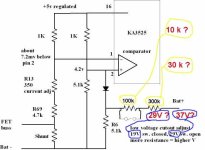
The signal from the shunt goes to a section in the KA3525 to form the current limiter circuit.

The low voltage cutout is combined into the same part of the circuit.

When the current tries to exceed the limit (35 amps), the comparator in the KA3525 starts to reduce the duty cycle of the PWM to keep the current at the limit.

If the battery voltage drops enough, the same comparator will reduce the duty cycle to prevent the voltage from dropping further. This results in a loss of power when the battery hits the LVC.

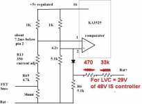
Here's a reverse engineered schematic of the current limiter / LVC part of the circuit.

From my calculations, the 100k and 300k should be 10k and 30k resp.
 

Attachments

  • brushless_controller_current_limiter_117 copy.jpg
    brushless_controller_current_limiter_117 copy.jpg
    31.3 KB · Views: 4,607
The original 48V IS controller has an LVC at 29V.

The 33k and the R6(5.1k) will be removed to de-activate the LVC so that the controller will work from 24V battery to 48V battery for my AL1020 ebike.
 

Attachments

  • brushless_controller_current_limiter_117 b.jpg
    brushless_controller_current_limiter_117 b.jpg
    24.3 KB · Views: 4,618
After studying the LVC and current limit circuitry in the X-contoller, it is found that LVC circuit would also affect the battery current limit for different battery voltage.

For example if the LVC is 29V and battery current limt is 20A for 36V battery for an X-controller.
.
If this X-controller is used for an 48V battery, LVC remains 29V. But the battery current limit would increase by an noticable amount.

If it is for an 60V, LVC remains 29V. But the battery current would further increase to an dangerous amount. In such case, the current is only limited by the battery and not by the controller.
 
The7 said:
After studying the LVC and current limit circuitry in the X-contoller, it is found that LVC circuit would also affect the battery current limit for different battery voltage.

For example if the LVC is 29V and battery current limt is 20A for 36V battery for an X-controller.
.
If this X-controller is used for an 48V battery, LVC remains 29V. But the battery current limit would increase by an noticable amount.

If it is for an 60V, LVC remains 29V. But the battery current would further increase to an dangerous amount. In such case, the current is only limited by the battery and not by the controller.

I have the 72v 35a model. I've run at 32 volts, 40 volts, 60 volts, 72 volts, and 80 volts. The full-time ammeter on my handlebars has never registered a different peak current between the different voltages. Temperature, though does seem to alter the current limit. Until the controller warms up, the limit is 33 amps. Once warm after about 30 minutes, the current limit is exactly 35 amps. When the temperature is about freezing outside, the limit is 31 amps. However, never has my meter registered any higher than 35 amps.
 
The7 said:
After studying the LVC and current limit circuitry in the X-contoller, it is found that LVC circuit would also affect the battery current limit for different battery voltage.

For example if the LVC is 29V and battery current limt is 20A for 36V battery for an X-controller.
.
If this X-controller is used for an 48V battery, LVC remains 29V. But the battery current limit would increase by an noticable amount.

If it is for an 60V, LVC remains 29V. But the battery current would further increase to an dangerous amount. In such case, the current is only limited by the battery and not by the controller.

I overlook that there is a diode between pin 2 and R6. So the above finding is wrong.

Correction: The LVC will NOT affect the battery current limit.
 
xyster said:
I have the 72v 35a model. I've run at 32 volts, 40 volts, 60 volts, 72 volts, and 80 volts. The full-time ammeter on my handlebars has never registered a different peak current between the different voltages. Temperature, though does seem to alter the current limit. Until the controller warms up, the limit is 33 amps. Once warm after about 30 minutes, the current limit is exactly 35 amps. When the temperature is about freezing outside, the limit is 31 amps. However, never has my meter registered any higher than 35 amps.

Sorry. You are right because I have overlooked the diode between pin 2 and R6.
 
Power rating for the 33k res in the LVC circuit!??

An surface mount res has an power rating of 1/16W (62mW)or 1/10W (100mW) as see at:
http://www.engineeringlab.com/resistorkits.html


For 48V battery:
Current thro 33k = 48/(33k+470+5.1k) = 1.24 mA
Power in 33k = (1.24m *1.24m)*33k = 50mW
Then 1/16W rating is OK. 1/10W rating is better.

For 72V battery:
Current thro 33k = 72/(33k+470+5.1k) = 1.87 mA
Power in 33k = (1.87m *1.87m)*33k = 115 mW
Then 1/10W rating is not enough.
It is better to use ordinary R of 1/4W


For 84V battery:
Power in 33k = 158 mW
Then 1/10W rating is NG.
You have to use ordinary R of 1/4W or higher.

For 96V battery:
Power in 33k = 200mW
You have to use R of 1/4W or higher.

So if you are going to UP-volt the battery voltage, you may have to change the rating of the 33k res.
 
Back
Top