Crystalyte Controllers - Repair and Modification information

*me locks back door*
I'll have a poke about and see if I can find anything tomorrow. I have a couple of old psu's and a few dead chargers out back :roll: I'll let ya know.
 
NickF23 said:
Is it ok to mix different voltages provided the lowest voltage caps are not exceeded by the battery input voltage? or should all caps be the same?

I think it's OK. As long as every cap has a high enough voltage rating, they should not fail. There would be an uneven sharing of current between different values, but I don't think this would be a real problem.
It would probably be better is they were all the same.
 
I produced a clone of Crystalyte 3 phase controller (72V,35A) about
6 months ago in Eagle, made my own 2- sided PCB (a lot of work!,) and made it running just like the original!
It took me about 1 week of working with Eagle in "BRD=board" screen only and
The result was a clone of the original controller.(better mosfets). All was done by looking where traces on the original PCB goes, looking at datasheets.
I also succeed in finding a supplier of a rather exotic NEC 3 phase
controller which was the only part I needed to finish it.
Was it worth it? Yes! I just wanted to understand it more and be able to repair my first original that failed. Now it is working again and the new cloned one as well, even cooler.
One thing I haven't finished. The schematics. I'm not very good in eagle and it would take me even more time to do it.
So if any of you want the BRD part of my eagle and can improve it or draw a schematics out of it I will post it to you.
At the moment my controller have 12 IRF1405 fets. The are cheap too! About 2 dollars each. So I guess wit a little of luck you can push it for 70A, 48V (fets are 55V, 5.3mohm,169A).
I use it on 33V dewalt pack, around 50A and it runs nearly cool.
I have soldered a lot of coper bars on PCB power traces so it will take this current with ease .
My controller is lighter, smaller and it has a real punch with my originally 600W motor. The motor has burnt el. controller inside but now is alive again with a help of my cloned external controller.
 

Attachments

  • 48V 70A controller.jpg
    48V 70A controller.jpg
    122.9 KB · Views: 1,788
Very sweet!
My hat's off to you.
If you don't have the schematics, did you simply strip off the components & scan in the pcb?
If I wuz going to go to all that work, I'd have to think about changing the shape like triangular or something to make a custom fit into an oddball unused corner of the bike.
But regardless very impressive work.
The enhanced performance makes it all worth it.
That's one hell of a first posting.
Your'e gonna have a tough time raising the bar. :lol:
 
Way cool, nemo. Kudos. :D

Mario Puzo once wrote about virgins: "Somebody has to be first..." :wink:
 
Excellent! 8)

I'd love to see a schematic. I only have bits and pieces from what I reverse engineered.
 
come on! post that soon! :D

I wonder how do you link your dewalt pack. Alot of people here are interested or have some (including me) and are curious to see what eyher ebiker did with those.

Doc
 
fechter said:
Excellent! 8)

I'd love to see a schematic. I only have bits and pieces from what I reverse engineered.

Thank You guys! Really thank You!

When I saw this great forum few weeks ago and I saw many things I already tried, I thought.... man....too late, you should have shared it 6 months ago!
but I guess it is not too late...

I'll post photos of the inside today.
I must admit that I missed one trace under smd logic IC and my friend with osciloscope helped me to find this single miss in about 2 hours. My spirit soured high when the motor spun for the first time.
It took me over 1 year to find somebody that would finaly supply exotic NEC 3 phase pre-driver in quantity of 10!.
How I did it?
brutal determination....
I redraw it in eagle bit by bit, just pcb, not even desoldering 90% of parts, What I could't see because of the small size I took picture with my digital camera and enlarged on pc, measured the rest with simple multimeter and guested some parts,some have numbers etc....so something like this...

it took me probably 5-7 days, 3h each night and I was really determined to do it since I was tired of ordering more controllers from the USA and not knowing why they sometimes fail.
My first failed about 3 years ago on my first project, scooter with BMC originally 600W motor on 63 saft D cells 9.5AH VH-D9500, over 75V,over 2kw.
 

Attachments

  • 2 scooters.jpg
    2 scooters.jpg
    201.9 KB · Views: 1,910
The7 said:
I am waiting too! :!:

Sending a few photos.


The only part that I substituted for non smd is NEC 3 phase pre driver IC.
All fited just in 4cmx6cmx18cm alu housing.
With better mosfets one doesn't need that much cooling, all is thinner and much lighter.
I went the hard way when filing all alu parts to make it as close to the original design as possible. Next time I would simplify the cooling system, it's rather overcomplicated on the original and my clone....Those who opened the controller probably know what i mean.
notice the 3 solid copper wires blended into the PCB under the 63V 220uf Cs. 50A or more is no problem here.
That's all for today . It's getting late here.
 

Attachments

  • IMG_8001.JPG
    IMG_8001.JPG
    100.2 KB · Views: 1,995
  • IMG_8004.JPG
    IMG_8004.JPG
    104.3 KB · Views: 1,988
  • IMG_8005.JPG
    IMG_8005.JPG
    113.4 KB · Views: 1,986
nemo said:
The7 said:
I am waiting too! :!:

Sending a few photos.

Thanks very much.

This is an excellent piece of work.
An fibre-glass board is better than the oiginal.
Apparently you go for low voltage and high current for this controller since you are using five 63V 220uF caps (c.f. three 160V 220uF used in fechter's).

By any chance, if you could post its schematic diagram?
 
TylerDurden said:
Nutball... :wink:

Soldering those SMCs musta been a picnic.

:lol:

I might do the schematics one day.
My good friend actually suggested the controller where the power part would be close to the original controller but the logic would be done with cheap and available atmel or pic processor.
It would be bigger project but he is positive that with the knowledge we have it would be the killer super duper controller.
This way one could tune his to his own liking.
Also the part count would be lower/weight/size lower and mods easier.

As to the high current and low voltage....
Mine was tailored for max punch when using 33V dewalt .At the time I was able to get cheap IRF1405. If I had IRFB4110 I would went for them as some of you did.
Soldering was ok. I actually prefer smd parts since there is less drilling.
The PCB:I used blue foil and laser printer to make it.
Then iron to stick the blue foil onto each side at one go! a and etched.
Now when I look what I did I know it was kind of mirracle to be able to finish the project .
I also must admit that my knowledge of circuitry is very limited and it would be on others to improve the schematics.

The sad story is that my scooter is illegal in UK now.

I got bliss folding bike instead and the power is not there yet. It has TARN motor.I opened it and the controller yesterday and will bring you photos of the geared motor and post some info in different section of forum soon.
So stay tuned!


:D
 
Amazing!

You have much more patience than me.

The idea of using a PIC is a good one. You could also possibly do a sensorless version that way. Most RC controllers are built this way. I suck at writing code, so I'll have to let someone else figure out that one.

I have thought of getting a small RC controller and grafting it to the Xlyte power stage.
 
i'm actually good at coding, coming from a software side of things (i teach computer systems - including assembler etc at uni). I'm just very light on the physical hardware side of things - al la building complex circuits etc.

Can anyone suggest a good primer book for learning about PWMs and brushless motor controllers (maybe "PWMs and Brushless DC motors for dummies" would be apropriate for my level of knowledge of hardware)

:roll:

the custom controller is fantastic! thats an excellent peice of work! I'm tremendously impressed. I take it you spent a lot of time redesigning where tracks went to minimise the size of the circuit? do u feel that it could be further improved in terms of layout?

Using a PIC or anything that would simplify the design of the controller would be excellent. I'm almost thinking that different form factors might be something good to have - in particular something that would attach to the chainstay (on the non chain side) - long and narrow - i doubt it would be possible though.
 
fechter said:
Amazing!

You have much more patience than me.

The idea of using a PIC is a good one. You could also possibly do a sensorless version that way. Most RC controllers are built this way. I suck at writing code, so I'll have to let someone else figure out that one.

I have thought of getting a small RC controller and grafting it to the Xlyte power stage.

I've learned that it isn't a good idea to use sensorless controller with scooters at all. Hall sensors are far superior when starting the motor with a big load. I even tried old and powerfull Aveox hall sensored 9for motors with hall sensors)RC plane controller. Motor spun fine but for some reasons no power was there at all.
It had MC33035 controller on it. Then I tried MC33035 and used catalog. circuitry , again no power, the motor spun up to max RPM but I could brake it with my hand.! right down!
But I saw MC33035doing just fine in bliss bike controller with 4 pole TARN MOTOR!
So for multi-pole motors MC33035 will not do, at least not when i tried!
Maybe as you suggest fit something like MC33035 in the xlyte power stage!
All take time and it may be wiser to actually use Xlyte schematics and for ultra power fans implement 24 IRFB4110 in smd size with no alu cooler at all. The problem is only the labor involved in making them.
For most people buying xlyte and desoldering IRFB 4710 and putting in 4110's is a better option than getting the parts and making controllers from scratch. like I did.
The only chance for making these controllers is to get a lot of people to share the cost of professionally made PCBs...
Also ordering sets of components in one go, getting some discounts and resending to all involved. If you would be interested just send me an email and I will count how many of you would like to make one and maybe it will be worth a try... :)
 
BiGH said:
i'm actually good at coding, coming from a software side of things (i teach computer systems - including assembler etc at uni)..

Seems that you, fechter and nemo are the trio in ebiking;
softwarer, hardwarer and manufacturer.
 
BiGH said:
..do u feel that it could be further improved in terms of layout?

I think I could shrink it to fit in 4cmx3cmx18cm alu tube.
From 4x6x18
With a little bit of work... 8)
 
nemo said:
I've learned that it isn't a good idea to use sensorless controller with scooters at all. Hall sensors are far superior when starting the motor with a big load.
Fully agreed.

nemo said:
I even tried old and powerfull Aveox hall sensored 9for motors with hall sensors)RC plane controller. Motor spun fine but for some reasons no power was there at all.
It had MC33035 controller on it. Then I tried MC33035 and used catalog. circuitry , again no power, the motor spun up to max RPM but I could brake it with my hand.! right down!
Great that you have done many experimental works.
You are an down-to-earth engineer/worker.

Most motors for traction (like ebikes) are designed with high-starting torque in mind. The spacing (relative phase-shift) between the Hall sensors and the motor windings is an important factor.

Motors for RC planes are designed with high rpm. Their loading torque is approx to the square or cube of the rpm. So they do not need high torque at low rpm.

nemo said:
But I saw MC33035doing just fine in bliss bike controller with 4 pole TARN MOTOR!
So for multi-pole motors MC33035 will not do, at least not when i tried!

If it works for 4-pole motor, it should also work for multi-ploe motors.
Does this MC33035 controller use Hall sensors?
 
Does this MC33035 controller use Hall sensors?[/quote said:
http://www.onsemi.com/pub/Collateral/MC33035-D.PDF

Yes it does.
I hate it didn't work...maybe the power stage, some current limiting...who knows! i even tried different controller made forsome scooters 20A,36V on BMC (inside again MC33035) and it did actually run scooter for a test drive but in some sort of non efficient mode! It felt like 300W instead of 600-700W, controller got very hot very quickly! I assume that the power stage wasn't fit for BMC motor.one explanation is that the fets weren't opening/closing quickly enough ...so the lost was on them!
I gave up soon and went to assemble the cloned xlyte (from powerpack motors.) I was just too fed up trying without the proper knowledge of what is happening... after so many failures to make one that really works with BMC.
w
 
nemo said:
i even tried different controller made forsome scooters 20A,36V on BMC (inside again MC33035) and it did actually run scooter for a test drive but in some sort of non efficient mode! It felt like 300W instead of 600-700W, controller got very hot very quickly! I assume that the power stage wasn't fit for BMC motor

The following are the important factors to match an BLDC motor (with Hall sensors) with an controller:
1) The phase-sequence of the windings and Hall sensors.
2) The spacing (relative phase-shift) between the Hall sensors and the motor windings is an important factor.
3) There are two spacing for Hall sensors in motor 60 deg or 120deg.

It seems that your case belongs to (2). If relative phase-shift is WRONG, the motor will draw excessive current and the power output is low. It is similar to run an 3-phase syn motor at an very poor power factor.

If the relative phase-shift is corrected, the motor should run OK.
 
i was going over this thread because i lost one of my controller drawings when we moved to oregon, and i took the time to follow it through. many thanks to fechter for the great work...

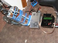
i am installing my new cycle analyst, and ran into a couple of things i thought would be worth passing on. for those not familiar with this new version of the drainbrain, check it out at ebikes.ca...

besides adjustable speed and current limiting, new features include an automatic gain switching circuit that permits much more accurate measurement of low power levels.

the speed and current limiting are achieved by pulling down the throttle signal by the cycle analyst. the new controllers justin is selling have the connector installed, but for those of us who want to add them to existing controllers, it is quite simple. you conect wires to the B+, Ground, both ends of the sense resistor, and a hall sensor connection is provided for hub motors to eliminate the need for a speedo magnet. for folks like me with a freewheel system a speedo magnet can still be used.


the reason i thought this belonged in this thread is a discussion of how the limiting is achieved. the KA3525 pwm chip in these controllers is used in a somewhat non-standard configuration. the regular pwm input of the chip is not used at all. all control is done via the soft-start capacitor input. this thread has previously discussed how changing the value of this cap can change the "attack" time of the throttle.

the cycle analyst just pulls down the throttle signal to achieve limiting, like fechter's adjustable current limiting system. in the crystalite controllers we have, the ebrake input does basically the same thing, and is tied to the soft start input through a diode that only lets it pull the signal down. the control signal from the cycle analyst can thus be connected to the ebrake line, since it is a linear control line. the latest controllers are different, but i doubt any of us has seen them yet.

using the ebrake line as the speed/current limiting input has some advantages; most of us have that line run up to the handlebars anyway for the ebrake, and it can be connected to the limiting control signal there, providing an easy place for a speed limiter disable switch. you can change the limit parameters via the software, but that takes time and lots of keystrokes. a simple switch connecting the limiter signal to the ebrake signal can be mounted where it is easily accessable, permitting instant enable/disable of the limiting functions.

some of you may see where i am going with this. suppose we don't want anyone else riding our bike beyond a certain power/speed level. we just need to make the switch a bit difficult to operate if one does not know the secret. suppose i need to prove to someone who thinks my bike was going too fast that it will not go that fast under power? i might put a hidden NC reed switch in a position where an easily removed magnet enables speed and power limiting, so that i can just pull off the magnet and the bike is suddenly legal :)

an aside; neither Justin nor I would encourage anyone to operate an ebike in an unlawful manner.
 
bobmcree said:
the reason i thought this belonged in this thread is a discussion of how the limiting is achieved. the KA3525 pwm chip in these controllers is used in a somewhat non-standard configuration. the regular pwm input of the chip is not used at all. all control is done via the soft-start capacitor input. this thread has previously discussed how changing the value of this cap can change the "attack" time of the throttle.

Thanks for this piece of valuable information.
Grateful if you give an more detailed explanation and with an circuit diagram if possible.
 
Alrighty, I've decided to post my problem here, for simplicities sake I've got a phoenix brute, 4840 controller, and 4 12V12AH batteries, and what I believe to be a dead controller. Making sure before I send it back:

I just tested the fets as done so by this guide, black lead to the negative on the battery, red lead to the 3 wires: My results with the meter set to 2000K ohm

Blue: 012
Green: 012
Yellow: nothing.

I can't get the yellow wire to show anything on the ohm gauge: no matter what setting I set, nothing happens. The only way I know I'm connecting is if I set it to V|... the voltage shows 52.6, which sounds about right for a charged battery voltage.

So is that it, blown controller? (Man, I so dont want to ship that motor.)
 
Back
Top