The7 said:From my calculations, the 100k and 300k should be 10k and 30k resp.
Yes, I think you are correct.
Now I have to go back and try to edit all the incorrect diagrams.

The7 said:From my calculations, the 100k and 300k should be 10k and 30k resp.
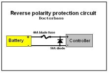
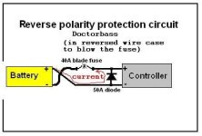
Doctorbass said:i installed a 40A fuse and a parallel diode on the controller to avoir fet burning again...the 50A diode is to protect against reversing polarity and is installed after the fuse.
The7 said:Doctorbass said:i installed a 40A fuse and a parallel diode on the controller to avoir fet burning again...the 50A diode is to protect against reversing polarity and is installed after the fuse.
Unable to view the exact config.
Wonder if you could post an diagram?
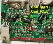
fechter said:There's a capacitor on the board that controls the ramp up. Stock is 10uf. If you replace it with a smaller one, like 1 uf, it will ramp up much quicker.
It might work to just remove it completely.
xyster said:It's 10uF on the other crystalyte controllers too. Doc replaced his with a 2.2uF capacitor.
http://endless-sphere.com/forums/viewtopic.php?t=1765&highlight=ramp
CGameProgrammer said:Doctorbass, could you post a version of that diagram in which the wires are swapped? What I'm not clear is, let's say Wire A goes from battery positive to controller ground, and Wire B is the opposite of course. Which wire has the fuse? Which direction is the diode?.
The7 said:xyster said:The7 wrote:
Did the 2.5s ramp time occur at no-load
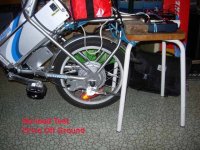
Wonder if you could do an simple experiment on your ebike 5304/20?
With the drive wheel off ground, give an quick FULL throttle and note
a) any delay time for the wheel start to rotate;
b) time for it to ramp up to no-load top speed: and
c) the battery current during ramp up.
I did the test myself on AL1020 using 36V at no-load.
Two ways to apply FULL throttle quickly:
1) Twisting the throttle to FULL as fast as I could;
2) Press the brake, turn the FULL throttle. Release the brake and the throttle will be at FULL.
These two ways gave practically the same results .
1) There is a small LAG. Seems to be the order of 0.1s.
2) The speed ramped up to no-load top speed (45 km/h) at a short period. Seems to be the order of 0.5s.
3) An digital ammeter and an analog meter were used to read the battery current. During the ramp up, the ammeter never exceeded 4A. So the current limit (20A) was not reached for such no-load test.
Comment:
1) It seems the order of 0.1s LAG is not desiable.
From memory of motor-cycling in young age, there was no such LAG feeling.
Thinking of changing the 10uF to 1uF may reduce this LAG.
2) When the ebike was loaded (road test), the ebike reached its current-limit (20A) every time at FULL throttle. In such case, the ramp up time (order of several seconds) will be dictated by the current-limit, and the top-speed by the battery voltage.
3) Don't think that there is any other ramp up circuit other than the "soft-start" 10 uF capacitor.
Would like to hear what is your experience.
NickF23 said:Finally getting round to upgrading my 48 volt controller to 72v. Could anyone recommend some caps? When I look on Digikey there are so many it makes my head spin The 20a 72v model apparently use 160v, 47uF, is this a good bet, is there any other specs I should be looking out for?
http://i106.photobucket.com/albums/m250/NickF23/104_0496.jpg
The7 said:The photo shows that it uses 100V 100uF caps which should be OK for 72V battery.
Doctorbass said:Also, you can buy a cheap picture camera(one use type) and take the caps inside(it is for the flash caps bank). Voltage are around 300V and 100uf or more. you can find some on ebay for 1$ each camera..
Doc
NickF23 said:The7 said:The photo shows that it uses 100V 100uF caps which should be OK for 72V battery.
Thats good to know, are there any other advantages of going with higher uf or voltage though?
NickF23 said:ok, you've inspired me to scavenge. Are there any other qualities that I should be looking out for in capacitors, or is it just volage and farads (uf)?
fechter said:You should also look for "Low ESR" capacitors. "Switching Grade" is another name for them. Lower equivalent series resistance reduces losses and capacitor heating. The filter capacitors in a switching power supply are usually good candidates.
I've seen some capacitors that got quite hot when used in a controller. I've had a couple of them explode on me (with subsequent FET failure :x ). By using low ESR caps, this can be avoided. Using more caps in parallel also reduces the ESR. Higher voltage rated caps tend to have lower ESR also.
Many smaller caps in parallel are better than a single big one. More copper in the leads and more surface area to dissipate heat. A few high frequency multi-layer ceramics in addition to the electrolytics will further reduce losses.