Definitive Tests on the Heating and Cooling of Hub Motors

When you say you're putting a fan to the controller, do you mean you're putting a fan on the controller housing, or forcing air *through* the housing.

Another thing worth testing is oil cooling the controller. I had good results with it, but lacked the setup to test it. I was running a 12 fet on 22s with the controller unlimited.
Only problem was I couldn't keep the oil from leaking.
 
Doctorbass said:
I have always wondered how much important is the added heat of the winding due to the reflected radiant heat from the aluminum side cover. Aluminum like many other metal are very good reflector of IR over 750nm... and even the black anodized aluminum is stll reflecting 80% of the IR over 800nm ... adn up to the long wave! ( dozens of micron wavelenght! )

That's a really good point I forgot to mention. You'll notice in the picture that the hub side covers are painted flat black with BBQ paint, which should also has a high emissivity. The roll of radiant heat dissipation is generally comparable with conductive dissipation in still air experiments, but in convective air it's a fair bit less. For instance, the 9C motor has a total radiating area of about 0.1 m^2. When the casing temperature is 70 degrees, ambient is 20 degrees, the radiant heat loss should be:

Heat = Boltzmann*A*(T2^4 - T1^4)
= 5.67E-8 * 0.1 *(343^4 - 293^4) = 37 watts.

Meanwhile the total heat being dissipated to ambient when the shell was at 70degrees based on the model with closed vent holes was about 150 watts, so radiation was responsible for just under 25% of the heat dissipation. With more active air cooling, then the role of radiant dissipation is reduced further as an overall percentage. So with the simple drilled holes, it's looking like it accounts for more like 15% of the loss, and with proper vents and blades it will likely be less than 10%.

However, with the ATF fluid cooling approach, we don't have any forced air convection and are reliant again on the smooth side covers to get rid of the heat, so the role of radiant should be more significant.

I can send you this paint if you want to give a try.
Doc
Thanks, I think that the black BBQ paint is probably good enough but if you want me to run a comparison to see if that makes a measurable different I could do so. I definitely DO want to compare painted vs. unpainted side plates at the very least, especially in the oil filled motor approach. So we'll add that to the bulleted list.

-Justin
 
auraslip said:
When you say you're putting a fan to the controller, do you mean you're putting a fan on the controller housing, or forcing air *through* the housing.
This is a small computer fan blowing air at the controller just like the airflow it would get when strapped to a moving bike.

Another thing worth testing is oil cooling the controller. I had good results with it, but lacked the setup to test it. I was running a 12 fet on 22s with the controller unlimited.
Only problem was I couldn't keep the oil from leaking.
You'll notice in the controller test graphthat I've got thermocouples on the mosfet, the heatsink, the capacitor, and the PCB power traces. The only thing that looks like it would benefit a bit from oil is the capacitor which was noticeably hotter, but the rest of the temps are all close enough that things in the controller are at pretty uniform temps. So the addition of oil would mostly just serve to increase the overall heat capacity. Adding a block of aluminum does the same thing with a lot less mess :)

-Justin
 
Absolutely fantastic. This can help us all run the smallest possible hub, allowing for pedal assistance at low speeds .

Also there are smoke sticks that you can buy that are intended just for this purpose.
 
With an open/drilled motor design, it seems the goal would be to simply exchange as much air volume to cross over the stator as possible to maximize cooling.

Possible now to test out the air hole porting that has been mentioned in other cooling threads. Center intake and perimeter exhaust holes on each side vs the cross cooling only (center one side -outer flow holes opposite side). Both with and without the fancy hole edges that add to flow. Internal veins also possibly a great adder to cooling.
 
justin_le said:
You'll notice in the picture that the hub side covers are painted flat black with BBQ paint, which should also has a high emissivity.

A good BBQ paint will have low emissivity if the company chemists have come up with a good formulation, because they want to keep the heat in not purposefully radiate it away. Highly emissivity is a double edged sword usually, because it's almost always has high absorptivity too, so that 37W doesn't consider how much it absorbs. Plus while parked in the sun it can directly cause a warm motor to start.

High emissivity/low absorption is what you want on the outside, and anodized aluminum is one of the few things that fits that bill, though I'm not up on what color(s) are best. On the inside you need low emissivity and high absorption, and that's tough too, but I remember while researching the collector for a solar hot air engine that there is one flat black BBQ paint making that claim. I can't remember the brand, but all that stuff was on a crashed hard drive and the backup was reformatted once solar panels became so cheap that LTD solar engines made no sense other than as novelties.

Get good ventilation going and the covers won't be very warm anyway. For a sealed motor with no oil, sure do everything you can if you have heat problems.

More efficient motors and properly sized motors are better answers, and if you have to suffer with the poor efficiency of common motors then don't over-drive them. Most heat problems are the result of improper settings on the controller. The most common is a phase/battery current limit ratio that is way too high, which is also a major cause of blown controllers. I realize these are OT, but it's high time these explanations come from the top. Add to the list the helpful hint that stop-n-go traffic is the most torturous condition on a hubmotor since each repetitive start from zero begins at 0% efficiency and how easy you are on the throttle makes little difference. If you're worried about heat get the bike started with the pedals.

Cooling is a great topic. Just lets not forget about reducing the heat generated in the first place.
 
Interesting topic. Stove and manifold paints are designed to help shed heat as well as keep stuff. They are typically made for surfaces that run much hotter then the outside surfaces of the modern gas BBQ.

I also would not think it would be much if any of a detriment if the surface became also more thermally absorptive.

One thing I do note when looking at aluminum alloys is the big variation in thermal conductivity of the various alloys. http://aluminium.matter.org.uk/content/html/eng/default.asp?catid=166&pageid=2144416529

Looks like there may be much better alloy selections for hubs and ones also to stay away from.
 
speedmd said:
One thing I do note when looking at aluminum alloys is the big variation in thermal conductivity of the various alloys. http://aluminium.matter.org.uk/content/html/eng/default.asp?catid=166&pageid=2144416529

Looks like there may be much better alloy selections for hubs and ones also to stay away from.

The holdup is from the surface of the aluminum to the air. Conductivity is so fast through the aluminum that the delta T from the inside surface to the outside surface would be tiny. The motor on my daily rider is mostly steel with one aluminum side cover, and in another high efficiency hubbie I have the only steel is a magnet backing ring, stator lams, and the axle. It doesn't make a hill of beans difference in heat transfer. In sealed form what matters is the surface area and its temperature, not the type of metal. That along with not having enough motor for the power input is why Itchynackers got a hot motor climbing the peak in near 0°C weather despite having oil in his 9C. The ultimate bottleneck is the outside surface to the environment, because our magnets can only take so much heat.
 
John in CR said:
justin_le said:
You'll notice in the picture that the hub side covers are painted flat black with BBQ paint, which should also has a high emissivity.

A good BBQ paint will have low emissivity if the company chemists have come up with a good formulation, because they want to keep the heat in not purposefully radiate it away. Highly emissivity is a double edged sword usually, because it's almost always has high absorptivity too, so that 37W doesn't consider how much it absorbs. Plus while parked in the sun it can directly cause a warm motor to start.

High emissivity/low absorption is what you want on the outside, and anodized aluminum is one of the few things that fits that bill, though I'm not up on what color(s) are best. On the inside you need low emissivity and high absorption, and that's tough too, but I remember while researching the collector for a solar hot air engine that there is one flat black BBQ paint making that claim. I can't remember the brand, but all that stuff was on a crashed hard drive and the backup was reformatted once solar panels became so cheap that LTD solar engines made no sense other than as novelties.

Get good ventilation going and the covers won't be very warm anyway. For a sealed motor with no oil, sure do everything you can if you have heat problems.

More efficient motors and properly sized motors are better answers, and if you have to suffer with the poor efficiency of common motors then don't over-drive them. Most heat problems are the result of improper settings on the controller. The most common is a phase/battery current limit ratio that is way too high, which is also a major cause of blown controllers. I realize these are OT, but it's high time these explanations come from the top. Add to the list the helpful hint that stop-n-go traffic is the most torturous condition on a hubmotor since each repetitive start from zero begins at 0% efficiency and how easy you are on the throttle makes little difference. If you're worried about heat get the bike started with the pedals.

Cooling is a great topic. Just lets not forget about reducing the heat generated in the first place.


I agree with everything in this mildly off-topic approach, and I personally think the folks with overheating problems driving 10-15x the motor design current into a hubmotor so that the system only works because the usage duty cycle is so low are kinda being silly about things, when an electric vehicle can deliver that thrilling performance/riding-experience you want all the time in a way closer to stable way if the stator was grown in radius a inch and/or grown in width another inch or so in whatever hubmotor you're using right now (possible exceptions to guys with a small handful of the very large yet also well designed hubmotor offerings out there). The penalty is like maybe 5lbs if it's designed right using light strong methods, and you just pretty much end cooling issues entirely once you've got a properly sized large electric motor for the task. For my roadbike that I'm setting up just a 200w assist (just enough to help my road-bike-fun-and-exercise rides stay-up with good in-shape riders if I pedal hard on), this means my cute 350w motor might be dragging around more weight than I need even though it's gotta be in the same weight range of the smallest made I think. Yet, on the other end of the spectrum, even the x5304 I used on an early gen of deathbike raced at the Tuscon deathrace wasn't nearly big enough to handle the 400amp 120v setup I was hitting it with. It just melted down in 3 laps in a smoking mess of disappointment, yet in Arlo's BMX, the exact same type of motor delivered a thrilling overly-wheelie-prone experience that was like the ultimate cross-town short wheel base maneuverable hard accelerating vehicle to rip through traffic with an it had no cooling issues at all in this usage model, so being larger would just be more weight for nothing but a tiny bit more range perhaps from efficiency improvements, but overall not worth the extra 5lbs to carry.

It's crazy the motor size thing. Rather than different brands of roughly the same size motor, I would love to see more branching out into the un-charted spaces for bicycle hubmotors. If you want something with magic pie diameter and 75mm width or whatever, because you want to spend most of your time cruising a 60mph on the highway hauling a utility trailer or something on your bicycle, a motor that does that easily and efficiently should exist. Likewise, if I want to just have 200w of help on my otherwise feather-light roadbike as just a mild edge to let me ride with my in-shape roadbiker friends without holding them up, I want a motor that's thermal limit is not much higher than being able to supply 200w of assist steadily without overheating, and have it be made with as much consideration to weight savings and quality as my dura-ace and ultegra components were given on the rest of the bike. I might be one of the few DIY electric bicycle conversions that has more money in the pedal drivetrain parts than the whole electric conversion expenses, and I'm wishing the motor was smaller. lol :) I think the available stuff isn't too far off the mark, things like the ebike classic hubs we run here are honestly pretty much in the right size scale for typical sane bicycle transportation uses. I just want to see the other ends of the spectrum also get supported better, the extremely high continuous torque efficient and still drops-in-a-bicycle-frame space, and the so tiny an light of a thin direct drive motor that nobody who wanted to fully power a bicycle without pedaling it would never even find it a useful amount of assist. Like a motor so small it's continous thermal limit is say 100w output, yet it's silent and super light and still efficient from growing a big very thing radius using spoked side covers or something to keep it extremely light while still having like a 5mm thick large diameter stator supported by some super light interior truss work structure connecting to the hub axle. This is totally on the level that is reasonable to make for exotic weight savings on roadbike parts that only shave like 25grams off the next step down part that costs $300 less, and does everything functionally just as well and will likely last longer, it's only crime is being 25grams heavier, and that's why the ultra premium weight savings parts exist. Riding a super super light roadbike is fun, feeling it surge forward with every pedal stroke fun, I would pay $1000 for a deeply well designed leveraging premium materials to be strong and light and efficient hubmotor that only outputs 100w continous for my roadbike, but it's too little power to interest most folks into bothering to make. Likewise, if I wanted to be a bicycle based large package courier or something, I might want a 4x width bigger radius than magic pie motor on my bike, so I can haul a refrigerator home on a trailer or whatever up hills at normal safe traffic speeds, and the rest of the time I just pay a stiff weight and no-load efficiency penalty on my efficiency while riding around unloaded and not requiring my motor to be so large. Maybe even have a second bicycle with a tiny roadbike hub for transportation when it's just yourself and you feel like exercise, and the huge motor bike sits until the person needs to haul a heavy item again or something. Like owning a pickup and an efficient sports car. Both can be very fast and fun, both can badly do the jobs of each other if you could only own one or the other, but rather than needing all the hassles of owning two full registered insured vehicles that need expensive maintenance etc, you just have a pair of bicycles that store easily in a small space in your hall way. Way lower footprint. Eliminating any restrictions on bicycle motor power levels would be a good start. That may be why this cooling concern is always a lingering issue in many high performance ebike applications. Some fools made 'laws' and suppliers put effort into product development that fits in those cruide guidelines rather than making what makes the most sense for the application.

Ok. So, back to cooling what we've got available, which does make fun and often thrilling to ride quick light ebikes, and should give them the ability to handle those 10x design power bursts for even longer duration and more frequent use, which is definitely something worth doing and conclusively finding what surface and what heat transfer methodology does perform the best.

Something I'm curious to know, is the simple equilibrium temp difference on the outside of the case at full speed no-load of a direct drive hubmotor just free-spinning in stagnant air around it for an hour or whatever to reach the practical thermal limit approaching equilibrium vs filled 1/3rd of the way up with ATF oil. I have a hunch the additional internal fluid friction making perhaps a substantial amount more heat from the higher full-speed no-load current, and the reduction in delta-T between stator and case, I imagine the no-load approaching equilibrium limit temp will be something surprising, like +20degC higher no-load ~equilibrium temp. However, I then also wouldn't be suprised to see it capable of handling 1.5->2x the continuous power out across the speed range despite starting with a no-load temp offset of 20degC. That outer case is going to get so hot on that oil filled one, it might be able to reach flesh-searing hot while the insides are still all operating at a safe temp. That lets a motor shed heat very effectively through both radiation and conduction from a higher ambient to case temp delta.
 
speedmd said:
Some interesting reading on the emissivity of aluminum / finishes topic.
http://www.molalla.net/members/leeper/coatbar.htm
http://www.infrared-thermography.com/material.htm

Rougher surface / more area / more heat loss. Anodize looks to be very good change for aluminum in this respect also.


That surface color difference is making a larger difference than I would have imagined at such low temps. Very interesting test. I would love to see tests back-to back on a sealed oil cooled motor being polished aluminum vs being sooty flat black. I'm guessing it's worth a substantial difference in thermal performance while indoors on the test dyno, but something tells me in the sunlight on a bright day that advantage may not be so large, possibly even a disadvantage.

Indoor and outdoor (sunny day) flat black vs polished oil filled motor test would be too much to ask my friend? Outside the scope of what you're seeking as results in this test series? I understand how much of a PITA it would be to drag your equipment outside on a sunny day and run power supplies and things to it and find out, but it's definitely an interesting test to a nerd like myself. :) I could believe that flat black coating absorbs >30w of additional heating from solar gain while spinning in the sun, but I could also believe it sheds that much or more even radiantly over the polished aluminum which would be absorbing a fair bit less solar gain energy, but paying a stiff radiant surface emissivity penalty by being a shiny low surface area finish.

Something tells me in motors that are powered at reasonable design levels (500w-750w or whatever), you're going to stay cooler shiny, and in motor pushing the thermal limits of the device, you're going to be better off flat black. However, this is only my $0.02 worth W.A.G.
 
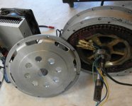
Well good news. It turns out that the dyno controller itself is fine, and that the problem was with a one of the phase wire connections in the system which had fatigued and broken even though it looked in tact. But by then I'd already taken everything apart and figured it was a good opportunity to add some ventilation holes to the dynamo motor itself since it'll be running pretty heavy duty during these tests too. The load hub is a Crystalyte 5302 motor, so known to be beefy but the phase amps it needs to sustain a given load torque are quite high with the fast 2-turn winding, and the 12awg phase wires get super hot.

View attachment 1

It's amazing how much more bad-ass a motor looks once it has a machined cover plate like this.

Drilled X5 Dyno cover.jpg

liveforphysics said:
That's so awesome your tiny controller lasted so long! Very cool! ... Could be quite a bit smaller with an alternate and more local cap and TVS diode layout it bet, perhaps even the same volume of the typical 6fets we run.

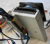
Well, to be fair I think the only reason it's held up so long is being being bolted to a massive 5" x 10" finned heastink with fan forced air cooling! Driving or doing regen on a 5302 is pretty unforgiving otherwise.
Dyno Controller Heatsink.jpg
 
That hole arrangement pattern looks very sexy and functional my friend! Wow! Nice job! Leave it to the guy who doesn't over-drive motors much to show most of the rest of us up when he finally wants to mod something to improve continuous power in a hub motor. :)
 
John in CR said:
Cooling is a great topic. Just lets not forget about reducing the heat generated in the first place.

I'm still waiting for them room temp superconductors. What happened to all the superconductivity excitement from a decade ago, did things just plateau at liquid nitrogen?

But yes, it's a good point. The subject of this set of tests is just to quantify the effects of different cooling strategies, it's not to suggest that active cooling is the right approach for good overall system design. However, knowing that existing hub motors will eventually burn up from currents and torques that are nowhere near stressing anything on the short term, and are far from saturation limits, it seems there is a lot to gain in the continuous power handling capability by better channeling the heat outside. The thermal mass of the hub motors takes care of power bursts and acceleration that people like, and in fact most day to day riding. But when you are going to climb a 1000m mountain pass over a modest 5-6% slope, most motors that would have no problem with that grade for short distances will be pretty near cooked near the top, and it needn't be so.

-Justin
 
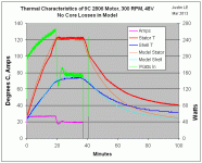
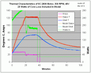
One thing that bugged me about the model in the earlier tests is that while the temperature rise data fit nicely, the model predicted a faster cooling time than what the data showed, and in fact the stator seemed to settle to a steady state well above ambient:
No Core Loss.gif

As I was preparing another round of experiments today, I noticed that when I had the 9C motor spinning on the dyno but not powered up at all, the temperature of the core started to climbing up and up, even though there was zero amps through the windings. Then I realized, shit, was all focused on the copper and forgot about hysteresis and eddie losses!

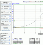
With the online simulator, you can actually read off the motor drag losses at any speed by setting the throttle low and seeing the negative watts on the motor power. In this case, with the 2806 hub spinning at 300 RPM, it looks like there are 29 watts going to the combined windage, hysteresis, and eddie currents:
2806 Core Losses.gif

So, I went back to the spreadsheet model and added a fixed 29 watts of motor loss on top of the I^R copper loss, and lo and behold, it suddenly fits so nice!
With Core Loss.gif

If anything, it's probably easier to do curve fitting and thermal characterization of the motor as it is cooling rather than as it heats up, since there isn't as much uncertainty in the total heat input and no need to measure or infer the 3-phase AC phase currents through the windings. That also means you don't even really need a dyno to do all these tests. Just heat up the motor when it is still by dumping a bunch of current through a phase winding, then after it's nice and not, spin it up unloaded and monitor how fast it takes for everything to cool down.

So if anyone wants to independently verify these results or do similar experiments, but lacks all the equipment and dyno, that would probably be just as effective a strategy.

-Justin
 
justin_le said:
Is there a particular reason why car transmission fluids have been the liquid of choice used by most people so far?

we are currently testing electric discharge machining (EDM) oil as a coolant in our (GM) hub motors. We had many issues with transformer oil weakening synthetics in e.g. shaft seals. We are hesitant using EDM oil, however, since flash points might be too low. What would you consider an acceptable flash temperature?
 
justin_le said:
If anything, it's probably easier to do curve fitting and thermal characterization of the motor as it is cooling rather than as it heats up, since there isn't as much uncertainty in the total heat input and no need to measure or infer the 3-phase AC phase currents through the windings. That also means you don't even really need a dyno to do all these tests. Just heat up the motor when it is still by dumping a bunch of current through a phase winding, then after it's nice and not, spin it up unloaded and monitor how fast it takes for everything to cool down.

So if anyone wants to independently verify these results or do similar experiments, but lacks all the equipment and dyno, that would probably be just as effective a strategy.

-Justin

Hi Justin, GREAT experiments! Try and get a University professor interested, and you are well on your way to a PhD in applied physics.

I think I recently performed exactly what you described above with my cromotor. See here: http://endless-sphere.com/forums/viewtopic.php?p=631379#p631379
 
Luke,
You might not be surprised by a 1.5-2.0 X continuous power increase with oil, but my money is on way under a 50% increase in the continuous case. The covers can only get so hot without risking the magnets and the glue holding them. That's the true limit, not an arbitrary temp at the copper, and that temp limit at the covers is the same with or without oil. Same cover temp means same heat dissipation. Sure there's some resistance moving the heat thru the interior layer of air, but the real bottleneck is at the exterior surface. eg I've had an outer shell reach over 100°C on a sealed motor with no discoloration of the magnet wire varnish. While oil might make the copper cooler, I wouldn't want the shell any hotter that it got on that occasion. That makes the heat dissipation limit the same with the only power difference being cooler making it a bit more efficient with oil, so more power. That's continuous though. In intermittent real world riding the advantage will be much greater. It still won't be close to the 2X or greater I expect from a ventilated approach that's blowing enough air that you can clearly feel air coming out of the exhaust at 300rpm. Every approach has to reject the heat to the environment. I've had great success bringing the environment into the motor to reject it directly without passing Go or collecting $200. :D

Justin,
Pretty cover. For future reference without true blades either inside or outside I believe many more smaller exhaust slots is the way to go, because the edges will be your centrifugal fan blades. Look at almost any radial blower as a guide. My big question is did you test it's effectiveness by simply spinning it up and putting your hand near the perimeter exhaust holes to feel if air is blowing out? Numbers are great but they don't make a 5 second feel test any less valid to help gauge effectiveness. You'll need those comparisons as you do different vented covers and blade/no blades.

It's great that you nailed down the iron losses and windage at 300rpm. Please do the same unpowered spinup on each variation so we can see the energy cost of different types of ventilation and the oil friction losses too.
 
Another thing that stuck out a bit odd in the data was the core temperatures in all tests had a small kink in them at just above 70oC, and a much larger one at 100oC.
View attachment 2

Turns out that I still have just an 8 step piecewise linear interpolation of the thermistor voltage in the CA3 firmware. I was meaning to go back and refine that at some stage but had forgot about it. Anyways, the look up table is perfectly accurate over the 15-70 degree temperature range, but between 70 and 100 degrees the straight line fit to the curvature gets a few degrees off, and above 100 degrees it gets really bad:
Piecewise Linear.gif

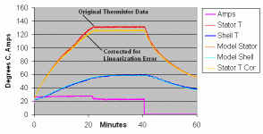
I'm fixing this now to a 32 step lookup table which should map things align well right up to 150 degrees, and in the meantime worked out an excel formula that undoes the CA's table calculation for temperature to figure out the thermistor resistance, and then recomputes the temperature based on the proper thermistor equation. The result produces a curve that looks much more like what was expected, and shows that the original peak core temperature was overstated by about 5 degrees
Linearization Error in Tests.gif
 
With a bit more confidence in the test apparatus, I decided to restart the experiments on the 9C motor that is painted black with drilled out side plates. The experimental procedure is to start with the motor at ambient temperature, spin it up to 300 RPM on the dyno, then power the 9C hub with exactly 40A of peak to peak current from a sinewave controller that runs in a constant phase current mode. This is done until the core temperature levels off at the CA3's thermal rollback, (130oC on CA = 125oC actual), it gets run there (at reduced power due to the CA limiting) until steady state temperature on the side plates is achieved, and then power to the motor is removed while it is still spinning at 300 RPM until the temperatures have come down.

The first thing I wanted to see was the effect of external forced airflow on the cooling. The motor spinning in still air is not quite representative of a motor on the road, so I put a large fan in front of the dyno setup. With a handheld anemometer I measured an air speed of between 11-14 kph around the hub, so similar to what you would have slugging slowly up a hill, and if anything fairly conservative compared the wind speeds you'd have on the motor in practice.

Here is the result with NO vent holes in the motor plates. The additional frontal wind speed doesn't have too much effect on the motor stator temperatures. Without the fan it takes about 19 minutes to hit 125C, and with the fan (albeit starting from a slightly lower ambient temp) it takes 22 minutes.

However, the effect on the motor shell temperature is a bit more significant, with the still air test the casing was at 67 degrees when the stator hit thermal rollback, while with the fan blowing the side plate was only 55 degrees at the same point. On the model, that increased the effective heat conductivity from the motor shell to ambient from 3.3 W/degree up to about 6 watts/degree.

Although the fan adds some level of variability in the test setup, I think I'll keep it present for the remainder of the tests because I want the results to be more realistic of what the motor is exposed to in practice, which is certainly not spinning in still air.
 
I like the fan!

I am also very surprised by the difference in temperature between stator and shell. Even though the heating up of the shell is positively corellated to stator temperature, it is nowhere near it in absolute temperatures. However, it is good to see that the influence of the fan extends beyond the shell. Obviously, the stator is able to shed some heat via the shell, even though it is not as efficient as the shell itself. Makes sense to me.

Will be very interesting to see if the vent holes make that process more efficient for the stator as well. Should be.
 
Great work Justin. I just can't get over how cool the shell is staying with what I consider to be a hot stator. I say hot because if you park that's 120° a millimeter or less away from the magnets roasting away at them. Your results are showing a much higher R1, thermal resistance through the air inside the motor, than I would have expected. I think my better results with sealed hubbies similar in design to the 9C are due to higher rpm, which thru greater turbulence and wind resistance inside would greatly reduce R1. It's really just more evidence against big wheels on hubmotors. If you extrapolate your results even an 80kg person with a 40kg bike with 26" wheels is going to melt his 9C on just a 5% grade. Just like wind resistance goes up exponentially with speed, a similar thing will apply inside the hubmotor and makes it better reject heat simply by running a smaller wheel at the same speeds. Higher speeds help even more in terms of heat dissipation by reducing R1 further and R2 as well.

Maybe I just lucked into a sweet spot with 16rpm/volt hubbies, and 74V nominal with wheels 20" or less. Far thicker and shorter copper in the windings means much less copper loss for the same power input. That high Kv and small wheel size is the one thing all my bikes share going back to 2008, including the high efficiency motors I run now at crazy power. The only motors I needed to ventilate are those with efficiency like your 9C but taken to extreme power. I've never been shy about taking my cargo bike on long rides with big loads up long climbs running 4X the power you're running in your test, and that's using a stock motor with roughly the same peak efficiency since the motor is the same diameter and slot and pole count. The surface area is pretty similar, so the only explanations are the Kv and wheel size, since there's no magical difference in the shell or stator design that would make it reject heat better than your test motor.

Does your power supply have variable voltage, so you could easily simulate a smaller wheel by increasing the voltage and loading it down to the same power output? Simulating a higher Kv motor isn't possible, but the smaller wheel size might be an eye opener to get people off of their big wheel fixation. My daughter's craptastic scooter ebike has a 20mm wide stator motor in a 16" wheel handles monster climbs many guys can only dream about, and it has no cooling treatments and even has polished AL covers with a motor of the same diameter, slot, and pole count as your test motor. We run it at 74V nominal with roughly the same Kv as your 9C. It's not her 50kg weight that does it, because that pig of a scooter and her 20kg battery more than make up the weight difference compared to a typical guy around here and his big wheeled bike.

Higher rpms has to be the key. I've been preaching smaller wheels forever and your test is proving it, because 300rpm is 37kph with a 26" wheel, and 1200W input shouldn't melt any properly geared DD hubbie unless it's bogged down under a heavy load or full stop starts are too repetitive. Sure you can ventilate it well and prevent heat failure, but that's just a bandaid without addressing the cause which is gearing too steeply with a big wheel. It must affect overall efficiency too.

Juice that baby up to 400-450 rpm with the same power input and see how much difference it makes in the temp spread between the stator and shell. I live in a mountainous area, so 5-10% are a fact of life on unavoidable roads, and I quickly found out I need to keep speeds up for both the controller and motor's sake. I run bigger loads so I like to maintain at least 500rpm up any hill with my 19-20" wheels, and as long as I do that I don't have to worry about heat problems except in downtown stop-n-go traffic.

This is all why the Chinese make so few electric motorcycles with typical motorcycle size wheels, and why Markcycle of Enertrac has been fighting heat issues for years despite using a massive motor.

John
 
Very interesting ! I agree with respect to motor sizing, but people are going to want to push the limits :wink: .....I would expect some fins machined into the side plates, and some oil in there to take the heat from the windings directly to the side cover, along with generous airflow, might be as good as pushing air through the motor.. mabye better because oil will provide more thermal mass to move heat from deeper in the windings (though action of some dippers, or is turbulence enough). air is somewhat limited in its heat capacity but if it can be moved effectively and with turbulance as John suggested and Justin seems to have proved with his amazing effort to quantify this!!
Bravo
 
Justin,
Can you make any recommendations yet as to whether using an internal temp probe/thermistor is an advantage over using the "hand method" on the covers? I'm pretty sure I know the answer, but coming from you would lend it more credibility.
 
Hi justin do you plan on ever putting a thermistor input on the cycle analyst ? it would be a really cool feature if we could see motor winding temps on the screen and also then if we could use that to do current limiting. that would be awesome. is that possible ?
 
Back
Top