Definitive Tests on the Heating and Cooling of Hub Motors

L_CaldwStatCatBaskReac.gif
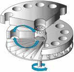
Would something like in the picture work ? Lets say the two thick plates are the side covers of the hub motor with the ventilation holes.
One cover has the vanes plus the thin plate (on the bottom of the picture) at the outside. When it spins the vanes fling air out,
creating a small vacuum in the motor. It will suck air in via the holes in the other side cover. Air will be forced to go through the stator.
I think it'd be better if the holes in the bottom side cover (the one with the vanes) are close to the middle.
 
Nice, Lebowsky.

I also remember an ES member using active fans inside the motor. Although I believe less moving parts is better, it will be interesting to see if a couple of 12V fans on the stator keep the stator cooler than some of John in CR's fins.
 
Justin,

Interesting that it's so linear. With the shell temps still hitting the same range my use of a hand as a tool and Methods plan to use an IR sensor on the outside are looking better and better. After one of the arguments last year I checked the calibration of my hand and right around 65-70° was always my "Motor is too hot, so what I was just asking of the motor is past the safe limit, so don't repeat." Sure real time data is better, but it's more than luck and coincidence that I ended up at the same temps at the shell as your rig.

The continuous case is always scary when I take a calculator to it. That's why I always try to throw in something extra on each new build. I'm still running my big high efficiency hubbie in sealed form and it's yet to trip the 95°C thermistor on the stator. I wonder how much the air scoops I put on the swingarm help with cooling. Sure I did them mostly to dress up an otherwise plain side, but at 60-80kph they must grab a lot of air to direct right at the motor shell.

SuperV air scoops.JPG
 
Lebowski said:

Would something like in the picture work ? Lets say the two thick plates are the side covers of the hub motor with the ventilation holes.
One cover has the vanes plus the thin plate (on the bottom of the picture) at the outside. When it spins the vanes fling air out,
creating a small vacuum in the motor. It will suck air in via the holes in the other side cover. Air will be forced to go through the stator.
I think it'd be better if the holes in the bottom side cover (the one with the vanes) are close to the middle.
Based on hjns's message, the vanes are attached to the side covers, they're not driven by a separate motor but spin with the hub
 
Lebowski, I am a firm believer that this is the best style of fan for hubs, mounted on the disc-brake side, with the fan-holes near the center of the hub. for the other side, I would guess having the holes near the rim?

file.php


This is the style of fan that bluefang is using
file.php


Mauimart
file.php


Recumpence
fan1_sm.jpg


Delco-Remy alternator, CS-144A truck alternator, 1986-present (27 years so far)
Delco%20CS144_400.jpg


GM 12SI style 140A
713-57294.jpg


Thud has one too, don't have the pic handy...

This is how I would locate the holes to make the best effect from a side-mounted vaned impellor:
file.php
 
The best air cooling mod I have seen on the forum was lowracer's forced air cooling of a big crystalyte.
I can't find a good picture, and the youtube videos have since been pulled down, but here is an earlier photo, later he included a shroud from the fan output with a really close fit to the side cover.
Here is the thread: http://endless-sphere.com/forums/viewtopic.php?f=3&t=24805&hilit=crystalyte+5404&start=25

file.php


[EDIT] Found a video, but not the one I was thinking of.
http://youtu.be/LEgMSDkWLyA?t=2m17s
 
It is indeed interesting that a number of us have reported this same ~60oC side cover temp as a 'things are getting too hot' guide. I use an IR themometer too but I suspect a secondary study may be in order to qualify the accuracy and linearity of the temperature sensing nerve endings in the palm of the human hand at temperatures over 55oC :lol:

John in CR said:
That's why I always try to throw in something extra on each new build. I'm still running my big high efficiency hubbie in sealed form and it's yet to trip the 95°C thermistor on the stator.
I was using a 100 oC themostat on my motors but have upped it to 110 now as I found 100 was right on the edge of what the motors would frequently hit and it became an annoyance that it would cut out all together. Realistically 120 would probably be a safe enough to prevent things getting out of hand and melting windings but I like to be on the cautious side as you can't control for how noobs will ride (thrash!) a bike. Justin's thermistor driven CA3 power limiting is a better way to go but I was doing this before that came out, plus it's universal in the absence of a CA or other monitoring so it still has utility IMO (perhaps at a higher temp for uninterfered riding 99% of the time)

Out of curiosity have you had you 95oC thermos cut out ? And if so how often ? I suspect you, like me, can attribute some of our sucess to the higher speeds we're doing and cooling effect of more/faster air flow over the covers (+/- your scoop)
 
Hyena said:
Out of curiosity have you had you 95oC thermos cut out ? And if so how often ? I suspect you, like me, can attribute some of our sucess to the higher speeds we're doing and cooling effect of more/faster air flow over the covers (+/- your scoop)

Only once in over a year, and that was stuck in severe stop-n-go traffic downtown after getting up to operating temperature with about 15km of generally up hill riding before hitting the traffic. That's with the smallest of my high efficiency hubmotors. The factory installs thermistors slightly away from the copper, so if it gets to 95°C, the motor is saturated with heat. The much heavier loads of 130-175kg scooters require temperature protection from the rider.

Thermistor placement.JPG

Those high efficiency motors are a different league. It's the spoked motors I've used since '08 that are essentially a Xlyte H40 with a 16rpm/volt Kv running a 20" wheel, that are comparable to common motors around here. I've run one sealed since '08, and developed the use of my hand with it. I have the identical motor running in ventilated form too, and it's been so abused without getting hot that installing a thermistor would be a waste of time. It gets warm but never hot up around the spoke flanges, because the dual sided exhaust doesn't stimulate flow the the gap. It sucks smoke into the intake holes at as little as 100rpm, and by 200rpm you can feel the exhaust flow.
 
speedmd said:
Impressive amount of work Justin. Huge results in "port added" cooling. Would like to see what potential further improvements are possible with the angled style porting shown here before.
file.php


The size of those holes is impractically small to help. The angled effects on the lips of the holes will cause virtually no effect on cooling performance IMHO, the relative speeds between the cover and ambient air just aren't high enough IMHO to make them influence airflow much one way or the other.

When a hole is very small, it creates an annuls of boundary layer turbulence around the vena-contracta of the orifice.

As an example of what this means, it means if you had 100 holes each with 1cm^2 of open cross section, it all adds to being 100cm^2 of open cross section. However, a single large hole with 100cm^2 would be capable of perhaps 10x the flow rate for a given pressure difference creating that flow, despite it being identical open cross section.


IMHO, those holes in the inside area of the cover that didn't cut through any braces will not be a structural issue. Each of those spokes is still way bigger and thicker and more material than the sketchy stuff on road bikes that's like just a handful of 1mm thick aluminum spokes to connect critical wheel components. I understand that it's got a big central mass bouncing on the bike frame, but remember the outer cover to bearing has both ZERO torque loading through that connection, as well as ZERO stator supporting through that connection, so the side cover only feels the loads of carrying the bouncing magnet ring, and the torque is transmitted nearly directly to the spoke flange, so the side cover assembly just has to support a magnet ring with iron backing, spokes, rim, tire etc, and I think even drilled out that much it's still easily 10x stronger than the rear roadbike hub I'm running right now that has been holding up great riding huge stair sets and singletrack on 700c wheels with extremely tiny spokes and a 216lbs fatty with a passion for destruction riding it.
 
Like LFP said. The "wetted perimeter" of tiny holes is lots more than the "wetted perimeter" of larger hole(s). Therefore, the friction is much greater with tiny holes, resulting in much less flow. Try blowing air through your screen door.
 
liveforphysics said:
IMHO, those holes in the inside area of the cover that didn't cut through any braces will not be a structural issue. Each of those spokes is still way bigger and thicker and more material than the sketchy stuff on road bikes that's like just a handful of 1mm thick aluminum spokes to connect critical wheel components. I understand that it's got a big central mass bouncing on the bike frame, but remember the outer cover to bearing has both ZERO torque loading through that connection, as well as ZERO stator supporting through that connection, so the side cover only feels the loads of carrying the bouncing magnet ring, and the torque is transmitted nearly directly to the spoke flange, so the side cover assembly just has to support a magnet ring with iron backing, spokes, rim, tire etc, and I think even drilled out that much it's still easily 10x stronger than the rear roadbike hub I'm running right now that has been holding up great riding huge stair sets and singletrack on 700c wheels with extremely tiny spokes and a 216lbs fatty with a passion for destruction riding it.

I mostly agree, but there have been drive side side cover failures due to the pedaling loads on the freewheel. I think the pedaling loads which are large and cyclic must be considered when placing holes in the drive side anywhere near the freewheel attachment.
 
This thread is flying. Every time I go to post it's moved on. I have wrote it over a few tea-breaks though.

The porting effect of small holes would holt the effects of a standard axial fan. Even the fans we are looking at want the biggest holes possible. Perhaps a bit of tube within a drilling might help enlarge the stressed edge.

I don't understand the picture. I'm all good till the blue arrows appear. One shows the rotor's location and rotation. The other two appear to have air circulating through the rotor shafts front bearing? I don't recognise this passage. Here is my sketch of what will happen. I have also omitted the motors guts, and just drawn the front and back bracket along with a fan.

Uploaded with ImageShack.us

The paddles on the spinning fan create a low pressure area behind them. A low pressure area further evacuated by the face of the next paddle passing through. Air in the area encaged by the paddles is drawn to the low pressure swept area and is then expelled by the face of the next paddle. This puts the area caged in by the spinning paddles under considerable vacuum, when compaired to the atmospheric pressure within the motor enclosure.
It is this low pressure area within the fan cage that draws air in from the motor casing. The air in the motor then drops below atmospheric, so cold air from outside will be drawn in through the back bracket. In turn it will pass through the motor, getting stirred about along the way. Before heading through the front bracket to be drawn to the blades that bat it out in to the atmosphere again.

I'm not 100% sure about the batting. It could be inertia and centrifugal forces that carry air through the vacuum and out the other side. It's perhaps unimportant.

Perhaps I'm just not seeing the first drawing properly. It appears to use some fan power to circulate air back and forth through the front bracket. This would still cause some cold air to enter through the back bracket, but much of the fans vacuum ability is lost to recirculating hot air through the front bracket.

The fan I pictured is an alternator fan. They have space issues too. It might offer a few mounting options. Even drilling 100mm out of the middle and putting it round the yoke like a skirt. Once you have that image in your mind, you can't help thinking that.........


Uploaded with ImageShack.us

If this wheel drove off to the north east, the vacuum made across the outer openings of my ducts would draw air from the core. This is more efficient than the ram air effect you would get riding off to the south west. A combination using a ram and vacuum seems sensible.
These are not aerodynamic. While the mouths are functional, the ducts length is just unwanted wind resistance. Ideally this duct design would run within an enclosed wheel. The sort of design that covers all the spokes, but was modified to encompass the ducts mouth. This barrier also gives us two sides of the wheel for ducts to run without interfereance between each other. You could run a number more ducts.
The issue next up is timing. As the wheel rotates the tyre vales dust cap goes from almost stationary to double the bikes speed during each rotation. The ducts will work well as there passing past 12 O'clock at double the bikes road speed. Not so well at 06:00. This would require a little drawing, And I have perhaps done enough

Heat pipes. How's that work? Should I be lubing my hubs spoke holes with thermal grease? Or looking to a new hub design that takes the spokes differently. Holes pointing in the right direction for a predetermined spoke pattern perhaps. Holes that could take studs, while the spokes have a socket for them. A way of mating them up close and thermally conductive. F1 hubs lol

The air round the motor does get exchanged a lot. What you really want is more surface area. Things like skirting the motors yoke with an alternator fan serve as heat sinks that cool themselfs.

Just looking at my wheel for inspiration. Could I actually use apposing spokes some cornflake packet and the gaffer tape to make and mount fan blades. Probably not. I live in a densely crowded area.
 
Luke,

You'd be surprised at how little flow is needed. My big vented motor has similar size holes, but only in one cover, not both.

Regarding the covers, I've heard about problems with mystery metal cast AL rims on hubbies such as the magic pie, and the metal of most hubmotor covers are even more questionable. I was wrong in the past about focusing so much on keeping the intake holes near the axle. Think about the intake area of a typical squirrel cage fan. Check out how Zappy does his now. I was also wrong earlier, and see now that the covers don't see the motor torque, but they they do support all of the weight the rear wheel sees except the wheel and rotor itself. The covers are the connection of the wheel to the rest of the bike, but unlike normal spokes the cast AL has no flex.

Farfle cracked his covers with motor torque impacts jumping a speed bump a few times with his motor as a mid-drive, so it only saw the motor torque. That was with larger "spokes" of aluminum left, and I can easily see road bumps and holes creating greater forces with use in wheel.

Big intake holes also greatly increase the chance or a small rock getting into the motor, and it only needs to be bigger than the magnetic gap to wreck a motor. I'm sure all of my vented motors would see greater flow with more intake area. I've just always been leery of big holes, and I get sufficient cooling without them. I've got an untested easily implemented idea to improve flow should I ever need it, so next time I'm just going with Zappy's approach plus thin slots as intake too.

Maybe I'm overly conservative, but that's what works for me. I feel like I've paid my dues with a few grand worth of blown controllers, which knock on wood seems to have finally ended. If I ever end up with a vented motor that gets hot, then I'll make some kind of change immediately, but I've been pleasantly surprised with cooling results beyond my expectations starting with the first motor I vented a few months after you were down. Maybe I can fine someone to be a Zero dealer down and give you a good reason for another visit. :mrgreen:

John
 
John in CR said:
Justin,
Interesting that it's so linear.
Well, I've now got the data at 0RPM and close to 500 RPM and that doesn't change the picture too much. The thermal conductivity from the stator to the shell can indeed be reasonably modeled as a linear function of RPM. It doesn't seem like at some critical speeds the turbulent air transfer suddenly has a more pronounced effect:

R1 versus RPM, 0-500 rpm data.gif

I wonder how much the air scoops I put on the swingarm help with cooling. Sure I did them mostly to dress up an otherwise plain side, but at 60-80kph they must grab a lot of air to direct right at the motor shell.
Anything that increases the air flow over the motor shell is sure to help keep the shell temperature down, which in turn helps lower the stator temp. But I don't know enough about fluid mechanics to say whether scoops like that necessarily increase the air flow over the motor surface compared to the flow that is present from the vehicle velocity. I have my doubts but it does look cool!
 
justin_le said:
John in CR said:
Justin,
Interesting that it's so linear.
Well, I've now got the data at 0RPM and close to 500 RPM and that doesn't change the picture too much. The thermal conductivity from the stator to the shell can indeed be reasonably modeled as a linear function of RPM. It doesn't seem like at some critical speeds the turbulent air transfer suddenly has a more pronounced effect:


I didn't think there would be some critical speed, but I did expect it to have somewhat increasing component like wind resistance, at least up to a point. I have zero experience calculating the convective heat transfer coefficient, so it's that's one number I took at best uneducated guesses at when I was crunching estimates for ventilated vs sealed. Thanks for spinning it up at different rpm, since it gives me a better "feel". Thank goodness it did increase, because flat would have left me searching for an explanation of how that's possible. After some more thought, for a sealed motor it probably starts to flatten out, since air is so limited in heat capacity.

I wonder how much the air scoops I put on the swingarm help with cooling. Sure I did them mostly to dress up an otherwise plain side, but at 60-80kph they must grab a lot of air to direct right at the motor shell.
Anything that increases the air flow over the motor shell is sure to help keep the shell temperature down, which in turn helps lower the stator temp. But I don't know enough about fluid mechanics to say whether scoops like that necessarily increase the air flow over the motor surface compared to the flow that is present from the vehicle velocity. I have my doubts but it does look cool!

I actually hope you're right and the effect is limited, because the last thing I want is for someone to have heat problems running the motor at the similar current limits and voltage (210A batt & 74V) with an equal or lower load than mine sees (175-190kg with plenty of hills). I don't want my results significantly better for an oddball reason. It's sealed so sure it warms up on 15-20km runs to the other side of the capital city blasting through traffic, but in 8 months at those controller settings I've only seen it get to a max of 60°C at the shell and have never tripped the 95° thermistor.

Your testing is going to prove ventilation is effective, and I want to contribute some info out at the extreme end of the scale. Since my motor is already wired for it, I'll just swap the PTC thermistor for an NTC type when I open it up for ventilation mods. I'm in the process of going from 20s to 32s, and getting my CA3 installed. Ventilation won't be far behind, with one-sided intake and exhaust, slots instead of holes, and interior blades mounted from the outside (if I can make that approach look okay on my other motor that is only waiting for blades.

John
 
Hi Folks

Air speed will change significantly when channel is reduced. No surprise here. some diagrams / formulas.

images

600px-BernoullisLawDerivationDiagram.svg.png

G200_venturi+effect+diagrams.jpg

images


The "wetted perimeter" of tiny holes is lots more than the "wetted perimeter" of larger hole(s). Therefore, the friction is much greater with tiny holes, resulting in much less flow.
No doubt. But the question still is, Holes vs no holes. Also with
drive side side cover failures
it may be the best option in some covers.

Try blowing air through your screen door.
Yes, there is much reduction , but not a total stall. Regardless of the hole size , you most likely will require some screen to keep debris out of your hubby, so we would be deciding on the mesh size rather than to use it or not use screen at all.

Agree with many of the concerns noted, but unless a complete re design / new covers are installed we are most likely going to have some less than ideal mods on venting.
 
thats all spot on for fluid flow through pipes, but open air tends to 'go around' restrictive areas, lessening this effect.
and mesh does hold the air up way more than the cross section would suggest, those cosworth DFV 80's f1 engines would gain 20hp on the dyno when you take the mesh off the ram tubes.

ill fish out the info from zappy and i testing the pie with 4 little 50mm computer fans internally and vented covers, we got to measure max continuous torque (holding 150deg c) -first sealed then drilled with the fans on and then off, and those little fans do seem to love all our trips to the beach.. :)
 
speedmd said:
Hi Folks

Air speed will change significantly when channel is reduced. No surprise here. some diagrams / formulas.

images

.

A simple formula for that picture above, that I didn't see in your post is:
AV=AV(sub 2)
If the area decreases as the liquid is moving though the pipe the air will have to move faster.
Try that in combination with John in CR's wind scoops. That would be the most ideal method of air cooling that seems simple and very effective. All you need then are holes that would take the already fast moving air and throw it into the motor. It would be much more effective than having the motor try to work to suck in the air.
I made a rather simple computer program that can calculate the amount of watts a surface can dissipate given a standard value for that material. As the surface area goes up the heat exchange, in watts, goes up exponentially. I'll post it up here if anyone wants it or thinks it could help? I bet it can be modified for multiple stages of heat transfer with some extra calculations and such.
 
thats all spot on for fluid flow through pipes, but open air tends to 'go around' restrictive areas, lessening this effect.

Fluids was many years ago but my understanding is that this has little to no effect on the pressures developed at the front of the opening as well as the compression ratio of the funnel itself.


those cosworth DFV 80's f1 engines would gain 20hp on the dyno when you take the mesh off the ram tubes.

Yes, correct! I understood this to be less than 5 percent loss. Better to finish the race than to run with a motor failing or teetering on destruction from swallowing gobs of rubber and other small track debris.
 
It's about pressure gradients. You need enough of a difference in pressure gradients for flow to move gases (in this case, air) from one side to the other. This has been proven already in John in CR's thread with only holes vs. fins which forces air into the motor and stator then exhausts it to the other side. Placement of the fins seems to be an issue with wind noise created. At high RPMs, having the fins positioned outside the motor case may cause an increase in turbulant noise vs. fins placed on the inside :?: It may be moot, compared to the actual whine of the motor itself, not sure.

Let's not forget about the other method of cooling. Using nonconductive fluid within the motor case. This method reduces any foreign object from getting through the holes and causing havoc in the motor casing.

Depending on the geography of your area (dry vs. humid, dusty vs. wet, etc.) you could choose an option that would best suit your motor.
 
melodious said:
It's about pressure gradients. You need enough of a difference in pressure gradients for flow to move gases (in this case, air) from one side to the other. This has been proven already in John in CR's thread with only holes vs. fins which forces air into the motor and stator then exhausts it to the other side. Placement of the fins seems to be an issue with wind noise created. At high RPMs, having the fins positioned outside the motor case may cause an increase in turbulant noise vs. fins placed on the inside :?: It may be moot, compared to the actual whine of the motor itself, not sure.

While the shape and angle of my intake holes may have some small effect, the intake of each of mine relies on creating lower pressure to "suck" air into the intake. With the one pictured earlier with the 5 blades in each cover, the material at the intake holes is quite thick, resulting in significant flow resistance at high rpm. It's so much that spinning it up while stationary the flow out of the exhaust drops way off as the motor approaches full no-load rpm. I never worried about it because the motor doesn't get hot in use, where the dynamics are different and those side ducts force at least somewhat greater pressure outside of the intake.

There's a lot of talk about optimizing, but all I want is good enough. 8" diameter centrifugal fans turning 800-1000rpm like my motors do can move incredible amounts of air, easily many hundreds of cfm. Not only do very high flow rates through the motor virtually guarantee debris in the motor, but it's also going to make it noisy and rob a lot of power. To make matters worse it robs more power at high rpm, where cooling flow is needed less.

Maximizing cooling air flow makes about at much sense as running a motor at it's maximum power. I think most lose sight of the fact that a motor is only 50% efficient at the maximum power it can produce. OTOH our stock motors work surprisingly well considering the primary heat source is in a sealed container with an insulating layer of air.

My Saturday crash has forced me to open my big motor to fix the wire harness, so while I'm in there I'll replace the thermistor with an NTC type to connect to my CA3, and I'm going to ventilate it too. I want to try something new with the exhaust vents, numerous straight radial slots. I may use the motor as a mid-drive at some point, and I want the freedom to run it either direction, so straight slots. I'll leave some slots on the sides to add blades from the outside, but I want to see if numerous slots will act enough like blades to create good flow. I'm pretty sure they will, since the slot edges will have a similar or greater velocity at the blade tips than my 3krpm 40mm blowers have. I'll still need the interior blades to increase velocity and turbulence at the exposed copper.

I won't get data like Justin, but stator temps pumping 25kw+ peaks into the motor on long rides and big climbs will have to suffice. That may seem contrary to my statements above about max power, but at 210A battery side limits the motor didn't show signs of saturation. That was at 20s, and my new controllers allow me to go to 32s, making 25kw input a certainty as long as torque throttle works with my dual controller rig. It won't be continuous, but still meaningful results. :mrgreen:

John
 
Back
Top