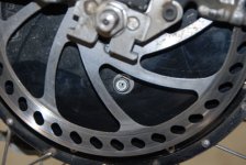
Definitive Tests on the Heating and Cooling of Hub Motors

Hey Dave and thanks for sharing those real world numbers!

intoworldsofuncertainty said:
Conclusion: Assuming I've worked all this out properly, the addition of oil as a heat transfer medium increased thermal conductivity by a factor of approx 2.5 times.
These results are almost a perfect corroboration for what I've been getting in the lab setup. With the closed hub, the conductivity from casing to ambient was between 4.5-5.5 watts/degree depending on the RPM and fan wind speed. So assuming that the oil does a near perfect job of transmitting heat from stator to casing, then we'd expect the total conductivity from stator to ambient in the oil filled motor to match that number too, as you got here.

So looking forward to seeing what results you come to with proper controlled experimentation. Would be great to see also, how much drag the oil adds to the motor. I personally haven't noticed much, but also haven't done any definitive testing.
It's actually quite easy to do. Just lift the wheel off the ground and record your no-load power and wheel speeds from very low throttles up to full throttle. Do that test with and without oil in the hub, and the difference is the power added from the oil fill.

-Justin
 
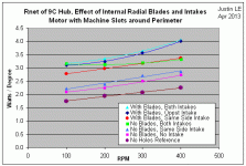
So over the weekend I got to complete the experiments with varying the intake position with the radial blades. By closing off the intake holes on the same side as the blades, and opening those on the opposite side, the conductivity improved by 0.3 W/degree at low rpms, up to 0.5 W/degree at 400 RPM.

I then repeated the test with both the left and right "intake" holes left open. I would think that with the same side intakes now open that pretty much all of the flow induced from the fan blades would come from the same side intake, and that any 'across the motor' flow from the opposite side would be effectively nullified. If the cross motor flow was key to effective cooling, then we would possibly expect a reduction in the overall conductivity from opening both sides up as that would eliminate the pressure differential between the two halves of the motor. However, the result was a slight further increase increase in conductivity, which suggests that anything which increases the overall air exchange in and out of the hub is beneficial regardless of the particular path:
Radial Blades Tests.gif

Notice too how in the two test with both sides open, (green squares and sky blue triangles), the effective conductivity at 100 RPM was identical with and without the internal blades. We can conclude that at low 100rpm speeds the effectiveness of the blades at increasing cooling air is negligible compared to the external wind air getting through the openings. However, as the RPM's increased the presence of the blades becomes increasingly apparent. If that trendline continues, you could see that at 500-600 RPM the difference could be several Watts/Degree.

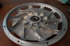
I also got a chance to twist the fan blades so that they are angled like this:
Sprial Blades.jpg

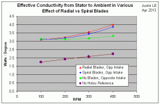
It performed slightly worse than the radial blades, though I can't be sure if that difference is within the margin of experimental error:
Radial vs Spiral Blade Results.gif

I was going to also spin the motor the other direction to see if forwards angle rather than a backwards angle on the blades would make a difference, but it seems any effect is likely to be marginal still.
 
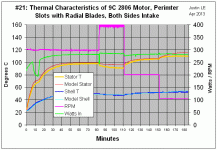
Also, I should point out in these tests with blades that the motors are never hitting the CA's thermal rollback point of 120 oC, and at the the higher speeds the stator core temps seem to stabilize under 100oC. So for those who aren't making sense of the watts/degree graphs, the improvements are quite tangible. The same hub that hit 120 degrees after 15-20 minutes without ventillation is now running continuously at like 90 degrees C.

Test21 Results.gif
 
Justin.

FWIW. Forward curved blades in radial blowers are generally used to produce higher volume flowrates for low-medium RPM. So you might see a benefit. They are more radial at the root and curve more forward near the OD...
 
Great work Justin!

I always have to look at your data a few times to soak it all in. Typing and deleting frequently. Awesome results...Holes alone are marginally effective because they just don't create flow, and blades make it quite effective even at 300 rpm. Bravo that you added 400rpm to the test, as it really highlights how higher rpm drastically increases cooling with blades and holes. Plus that's with a 9C which has precious little room for blades. My motors have more room for blades, and for years my typical cruising speed has been around 600rpm...with HubMonster it's more like 700-750 typical. I'm sure those factors more than make up for the smaller cross sectional area intake and exhaust. BTW, yes my no load rpm was over 1krpm.

Maybe the way I angle my blades so they aren't perpendicular to the side covers works to push air at the end windings pays good dividends, but I with so little room it may not be worth the effort to test on a 9C.

For your active fan testing, if you end up buying a bunch of those 40mm centrifugal blowers, I'll take 20-30 if it helps you get to a bulk discount. I need to order some more CA3's anyway. They don't move a lot of air at only 4cfm or so, but I think they're ideal for our purposes in motors, controllers, battery bays, etc, because they're far more tolerant of outside disturbances compared to axial fans, and blowing air a 90° to the intake is perfect for mounting on the stator spokes, drawing air into the motor (one sided intake for sure), and blowing a turbulent flow at the stator steel. I have no doubts about it working well. My motors are difficult to rewire, so I never wanted to do it just to add a temp sensor or wires for fans.

For the oil cooling I'll just shut up and watch. All I care about is how closely the shell temp mirrors stator temp, and how far you're willing to go in roasting the magnets and their adhesive.

John
 
Great work Justin.

No one can say now that holes and fan blades don't work. Significant improvements over the stock sealed case. Thanks for sharing this.

Interested in what oil will do also, but I have many questions still on blade quantity / hole size options and optimization of blade placement factors. With both intake and exhaust holes clearly working as such and very little drag recorded, I am thinking it possible the fan is stalling due to too small a intake area. You see this with any blower or vac, as you move a hand slightly over the intakes the rpms increase audibly. You may be starving the beast. Also, I would think it critical that the blade tips contact the case fully. Having blades not close off at the tip where they are moving the fastest may be a major change that effects their performance much more than expected.

For placement of blades, I would think it may be best if tried so that they would be right at the leading and also at trailing edges of the outer cutout holes. Also if not possible to add more center holes, it may be possibly to add ones next to existing center holes along the edge of the fan blade path so they would act as more of a radial slot type opening with added flow so they would not as easily stall the fan. The last question I have with regard to the blades is the quantity. Are five enough, fifteen too many. Perfect case to study loss factor when you have time to get back to it.
 
Justin, Some questions for you:

1. In your graphs you show the "Stator T". but you installed thermistors on the stator AND under the copper/winding:
justin_le said:
Then for the inside motor winding temperatures, we ground some slits in the axle as others here have done and used these grooves to embed some 10K thermistors, one directly on the copper and another just under the lamination stack:
file.php

... this first order model also suffers from the fact that the copper windings, stator, and side cover are all lumped together and assumed to be at uniform temperature.
So are you also capturing/representing data for the copper/windings temp or just the stator, or are you somehow combining them? I'd be curious how close those temps are, and how much the windings temp fluctuate in comparison to the stator.

2. Do you know why the Stator T drops so much more than the model when the motor is running at 400 RPM?
file.php

Can you say more about how you are calculating the model(s)? Do I understand correctly that one of the goals of this project is to create models for each type of cooling method for use in the simulator? If so, will there be specifications for each technique, like "30 1/2" holes around the perimeter".

3. Finally, can you explain how the simulator currently calculates the "Overheats in: XX min", specifically what temp represents overheating? 80C? I've always wondered and have found the data very useful in any case! [edit: nevermind, found explanation on simulator!] PS. Thanks for the link to: On the Saturation Current of Hub Motors & Simulator Accuracy. Another buried gem!

PS. I'm not sure what your plans are for oil cooling but I think there's general consensus in these tips:
- Use Dextron III ATF, inserted via hole/vent near the axle
- Seal the sidecovers and wirehole with ATF gasket maker, such as permatex
- Cover the halls with that sealant or JB weld
I'm sure you'll come up with a much better method tho! :wink:
 
GCinDC said:
1. In your graphs you show the "Stator T". but you installed thermistors on the stator AND under the copper/winding:
So are you also capturing/representing data for the copper/windings temp or just the stator, or are you somehow combining them? I'd be curious how close those temps are, and how much the windings temp fluctuate in comparison to the stator.
Hey great question. I'm only looking at the copper temp. Early on I measured them both briefly and they were within a few degrees, but that was after the motor had been stopped and settled a bit so perhaps during the run when most of the watts are originating from the copper that there is more of a differential. I'll find out next run.

2. Do you know why the Stator T drops so much more than the model when the motor is running at 400 RPM?
Yes indeed, it's because the thermal conductivity with both side holes open is no longer linear with RPM. In the model, I've just got a straight line 1/R vs RPM dependancy for each of the 3 resistance terms. If I change that relationship slightly so that the lines cross the 400 RPM data points, then the model will be spot on at 400 RPM but show even larger errors at the other RPM's. If I change the model so that the conductivities have a 2nd order RPM dependence, then I think it would match spot on over all the speed ranges. I may do that later this evening.

Can you say more about how you are calculating the model(s)? Do I understand correctly that one of the goals of this project is to create models for each type of cooling method for use in the simulator? If so, will there be specifications for each technique, like "30 1/2" holes around the perimeter".

That's indeed one of my main goals, although it would have to be understood as 'ballpark' in terms of choosing the technique. Say one option for holes on one side, another for holes on both sides, and another for holes with blades. That's part of why I want to see how much of a role little variants play. The model itself is based exactly on this:
file.php


Where the 1/R1, 1/R2, and 1/R3 terms all vary linearly with RPM based on the steady state temperatures, and the heat input is calculated from the temperature corrected I^2R copper losses plus the hystersis/eddie core losses at that speed based on the no load current data.

3. Finally, can you explain how the simulator currently calculates the "Overheats in: XX min", specifically what temp represents overheating? 80C?
It's 150 degrees, as explained in the FAQ text under the simulator. But it's based on a static non-rotating motor tests and doesn't seperately take into account the stator vs the shell, so is only intended to provide a ballpark relative figure and not to be taken literally in any ways. The main goal was just to give people a reality check when they plug in a 96V 60A setup to a hub motor and see many kW of power and go SWEET! That's what I want!

I've always wondered and have found the data very useful in any case! [edit: nevermind, found explanation on simulator!] PS. Thanks for the link to: On the Saturation Current of Hub Motors & Simulator Accuracy. Another buried gem!

That's another set of tests that needs to be resumed too, and brought into the simulator model. In the meantime, we've been meaning to make the lines go fuzzy or vanish when the model is predicting a phase current that is higher than the saturation point of the motors, so that people again won't take that literally since it's out of the bounds for what is modeled.

-Justin
 
I can appreciate very much your craftsmanship making those fins, Justin. Good job.

I'm planning on venting and finning my hubmonster when it arrives, but I am thinking it may be easier to order some 3D prints of the blades to be fastened on-- should it prove advantageous. Do you guys think that it is best to have "single-thickness" "sheet" fins such as those above or "filleted hump" or "3d" fins shaped similar to an ocean wave? If there is a cheap enough, 150C rated 3d print material, it could simplify the process and possibly (if plastic) be a bit less destructive to the motor if something was to fail and fall off. It would also help maintain a balanced motor since all the parts would be identical in mass and more predictably aligned (my motor will get up to 1300-1400 rpm at times)
 
Great point hillzofvalp

Outside of covers have some great potential to catch significant amounts of air.

Would be great to scan existing covers internal/ external and stator externals to get the original envelope /shapes digitized to make it easy to mod into a left side and right side fan / motor covers. I would think a printed fan would glue/screw on well to a cut out motor cover.
6935843-0-display.jpg


Possibly make a complete side cover in 3d. The standard plastic should certainly be strong enough to test out. Shape something like?
Transonic-single-stage-axial-fan-with-high-aerodynamic-loading-levels.jpg
Titanium is optional. :p
 
Hello,
I'm really interested by your results Justin, thanks to share your experiment and results !

I'm thinking since few month ago, to add some holes in my Enertrac Hub to prevent it to overheat after 10km of ride. (first generation of enertrac hub without cooling holes on covers)
I red all the thread and it appears clearly that blades add a non negligible flow inside the hub ; and also I agree with your proposal "speedmd", on the outside of covers, but it require your motor to spin at an high speed to be efficient ?

So I'm split between two solutions.
- Drill x8 basic large holes (diam:35mm) on both sides (as proposed now by Enertrac) and maybe add a "wave turbine helix" on external of one cover to catch more air, or a powerfull radial blower in front of holes...
OR
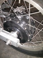
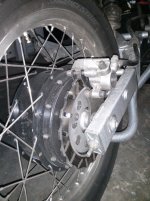
- Implement the Justin results and drill an "advanced" holes patern with intake hole on one side (I can't on the other side due to disc mounting) plus some perimeters slots on both sides and plastic blades inside. But the Enertrac hub design don't allow to drill big holes located at the center due to the large ball-bearing ; and I don't know exacltly the free space inside for blades (yes, I had to open it).
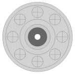
I think i can drill x10 15mm diam. holes at the center. I'm not convinced that x10 15mm intake hole (on one side) + blade + perimeter slots on each sides will be more efficient than x8 35mm basic holes on each sides.
I've draw two diagram on scale, to realise.
What's your opinion ?
 

Attachments

  • IMG_20130417_203256.jpg
    IMG_20130417_203256.jpg
    264.4 KB · Views: 5,948
  • IMG_20130417_203218.jpg
    IMG_20130417_203218.jpg
    260.4 KB · Views: 5,948
  • aircooled_basicholes.jpg
    aircooled_basicholes.jpg
    138.3 KB · Views: 5,948
  • aircooled_blade.jpg
    aircooled_blade.jpg
    143.7 KB · Views: 5,948
piwhy,
Your Enertrac motor has angled stator slots. The direction of that angle should determine which side of the motor is the intake, not which is more convenient. You do not want to fight against the natural cross flow through the magnetic gap. It's not much flow, but once you have an intake of fresh air, then any flow through the gap is beneficial.

Speculators need to let go of the idea that exterior axial blades are going to create a significant flow when subjected to an air flow coming from 90° off axis. Take 2 fans and put one in the flow of the other turned at 90° and see for yourself how much the flow of the 2nd fan is disturbed. It doesn't matter if you want to call them scoops or blades, the effect has been calculated before and the pressure differential was shown to be minimal even under ideal conditions.

Justin,
Apparently the difference between exhaust at the perimeter and attempting to exhaust through round holes away from the perimeter is still not appreciated. Can you do a run with perimeter exhaust slots closed?

John
 
Justin,
Apparently the difference between exhaust at the perimeter and attempting to exhaust through round holes away from the perimeter is still not appreciated. Can you do a run with perimeter exhaust slots closed?

John

I second that thought. Hole type and distance above/ below magnet should be optimized. Not sure how much a turbine style side covers could add. With the right style air deflectors and potentially using the air flow off of and around fatter tires, it could be significant or poor depending on execution. Agree, you would want to help the cross flow/have one side create higher pressure but not sure how much that adds. Good project to 3d print some working ideas and see where it goes. Solidworks, I see has available a heat flow app. Is anyone familiar with it. Wondering if it can model this. Mold flow is the closest I have come to this type of modeling. Would save much testing if one could model it. I see China electric motors is doing it.
2010072311551357133.jpg

2010072311540031867.jpg
 
John in CR said:
piwhy,

Speculators need to let go of the idea that exterior axial blades are going to create a significant flow when subjected to an air flow coming from 90° off axis. Take 2 fans and put one in the flow of the other turned at 90° and see for yourself how much the flow of the 2nd fan is disturbed. It doesn't matter if you want to call them scoops or blades, the effect has been calculated before and the pressure differential was shown to be minimal even under ideal conditions.

John

Ok, but if the exterior axial blade is embraced by an air forced duck (natural or not) almost like on the old drum brakes, the air flow coming from 90° off axis isn't a problem isn't it ?
I agree that's not easy to fit on an e-bike but it could be conceivable on a larger hub on a motorcycle...
 
John in CR said:
Speculators need to let go of the idea that exterior axial blades are going to create a significant flow when subjected to an air flow coming from 90° off axis. Take 2 fans and put one in the flow of the other turned at 90° and see for yourself how much the flow of the 2nd fan is disturbed. It doesn't matter if you want to call them scoops or blades, the effect has been calculated before and the pressure differential was shown to be minimal even under ideal conditions.
This.

For a large scale example of the problem of disturbed airflow, some jet engine installations are subject to "compressor stall" when the airflow is too far off axis. The TF30 in the F14 was notorious for this. Essentially axial fan blades are little wings and like all wings they only work for limited ranges of attack.

For a hub motor a centrifugal fan approach may be better, but a look at actual centrifugal compressors like turbochargers or some jet engines shows careful attention to managing the direction of the inlet air so maybe not. Also, most fans axial or centrifugal spin at much higher rpm than hub motors. Perhaps for a hub motor we should not be looking at jet engines but instead take design inspiration from devices that operate more nearly at the airflow and rotational speeds likely on a bicycle.

Like this Dutch_windmills,_Holland,_ca._1905.jpg, or this:Dutch_windmill_1001777c.jpg.
 
Nice. This is where I grew up...

file.php
 
Hi Henk

Love your part of the world. Great bike paths everywhere. In the north the whole place looks like a Renascence painting. All the little lambs running around. Hope to get over there for the next eleven cities race.

Ideas are a fragile thing. Here we should exchange, in a positive light what may work. This has fallen off the tracks a bit. We know now with the help of Justin and several others that internal fans and venting work well. Not perfect and with lots of other problems that come with opening the motor shell to debris. But they work extremely well with very small amounts of air and power loss.

With that said, we are not looking for fan propulsion. We are looking to maximize heat loss, so even a small gain in flow in the correct spots can have major impact on the motors ability to not burn up.

All ideas should be entertained until we know more, Much more.

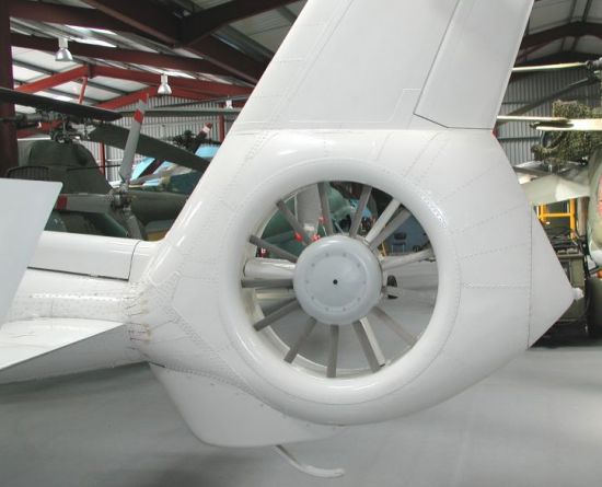
Tell a heli pilot he should not fly because his tail rotor will not work because it is 90 degrees from the air flow path.
fenestron.jpg

I am sure the brain storming sessions then sounded much the same. :p
 
So I'm split between two solutions.
- Drill x8 basic large holes (diam:35mm) on both sides (as proposed now by Enertrac) and maybe add a "wave turbine helix" on external of one cover to catch more air, or a powerfull radial blower in front of holes...
OR
- Implement the Justin results and drill an "advanced" holes patern with intake hole on one side (I can't on the other side due to disc mounting) plus some perimeters slots on both sides and plastic blades inside.

Hi Piwhy

I would say it is too early to decide. Lets see what comes out of the other cooling methods Justin has planned. If air is the way to go, I would see trying at least three parts and all their iterations. Stator diverters, as well as internal and external blades with all the drilling iterations and options explored in a DOE. Thinking with replacement covers, you could merge the internal/ external blades into a suitable support structure. Agree, fan design is critical to get it to work at the low rpms we need it to. Beauty of the ground work Justin has laid here, is he has carefully laid out the responses vs suitable RPM range.
 
piwhy said:
John in CR said:
piwhy,

Speculators need to let go of the idea that exterior axial blades are going to create a significant flow when subjected to an air flow coming from 90° off axis. Take 2 fans and put one in the flow of the other turned at 90° and see for yourself how much the flow of the 2nd fan is disturbed. It doesn't matter if you want to call them scoops or blades, the effect has been calculated before and the pressure differential was shown to be minimal even under ideal conditions.

John

Ok, but if the exterior axial blade is embraced by an air forced duck (natural or not) almost like on the old drum brakes, the air flow coming from 90° off axis isn't a problem isn't it ?
I agree that's not easy to fit on an e-bike but it could be conceivable on a larger hub on a motorcycle...

A directed air duck / air dam is exactly the kind of thing I hold onto as a backup plan if I end up with a hot motor after opening it up for ventilation. I don't include it in the initial plan, because It will rob aerodynamics and is easily added after the fact, so it stays in my hip pocket. If needed, I I love the idea of increasing pressure outside of my intake holes or slots, along with changing the air flow that is otherwise speeding by at 90° to the direction of intake. It's easy to envision ways to construct it so debris falls away instead of being deflected into the motor. It's another benefit of my one side intake, one side exhaust approach, since on the exhaust side I can put a similar structure facing rearward to decrease pressure outside of the exhaust vents and enhance flow.

The nature of our intake makes it probably the most compromised part of our air flow system. To help understand how compromised our intake is, think of a common air flow system with a centrifugal fan and an a large pipe feeding the intake, even a nice smooth 90° bend in the pipe too close to the intake can reduce flow as much as 50%.

John
 
speedmd said:
Hi Henk

Love your part of the world. Great bike paths everywhere. In the north the whole place looks like a Renascence painting. All the little lambs running around. Hope to get over there for the next eleven cities race.

Ideas are a fragile thing. Here we should exchange, in a positive light what may work. This has fallen off the tracks a bit. We know now with the help of Justin and several others that internal fans and venting work well. Not perfect and with lots of other problems that come with opening the motor shell to debris. But they work extremely well with very small amounts of air and power loss.

With that said, we are not looking for fan propulsion. We are looking to maximize heat loss, so even a small gain in flow in the correct spots can have major impact on the motors ability to not burn up.

All ideas should be entertained until we know more, Much more.

Tell a heli pilot he should not fly because his tail rotor will not work because it is 90 degrees from the air flow path.
fenestron.jpg

I am sure the brain storming sessions then sounded much the same. :p

The tail rotor doesn't work very well once there's a fast flow at 90°. That's why it has a tail and rudder. That's also why the tail rotor is outside of the swept area of the main rotor, since the main thrust would render the tail rotor almost useless at low air speeds where it is needed the most for fine control.
 
A directed air duck / air dam is exactly the kind of thing I hold onto as a backup plan if I end up with a hot motor after opening it up for ventilation. I don't include it in the initial plan, because It will rob aerodynamics and is easily added after the fact, so it stays in my hip pocket. If needed, I I love the idea of increasing pressure outside of my intake holes or slots, along with changing the air flow that is otherwise speeding by at 90° to the direction of intake. It's easy to envision ways to construct it so debris falls away instead of being deflected into the motor. It's another benefit of my one side intake, one side exhaust approach, since on the exhaust side I can put a similar structure facing rearward to decrease pressure outside of the exhaust vents and enhance flow.

Agree, that a ducting is a good approach to charge the intakes, turn the flows and create higher air pressure changes. Lots of good designs in dust collectors that could apply also to the debris separation. Husky uses a great design on there chainsaws to help keep the sawdust out of the air box. Also think you can dam up the exhaust ports so they would mostly dump toward the rear and be shielded in the front. Intake / center openings/ fan, diverted /dammed in the rear and open /collect air in the front. Lots of exotic low rpm spiral type fans can be tried if starting from scratch. Less option on mods for certain. At ebike speeds, I would not rule out any of the low speed fan design options for cooling without some test data showing the effects across the rpm/speed range. Interesting design challenge for certain.
 
speedmd said:
So I'm split between two solutions.
- Drill x8 basic large holes (diam:35mm) on both sides (as proposed now by Enertrac) and maybe add a "wave turbine helix" on external of one cover to catch more air, or a powerfull radial blower in front of holes...
OR
- Implement the Justin results and drill an "advanced" holes patern with intake hole on one side (I can't on the other side due to disc mounting) plus some perimeters slots on both sides and plastic blades inside.

Hi Piwhy

I would say it is too early to decide. Lets see what comes out of the other cooling methods Justin has planned. If air is the way to go, I would see trying at least three parts and all their iterations. Stator diverters, as well as internal and external blades with all the drilling iterations and options explored in a DOE. Thinking with replacement covers, you could merge the internal/ external blades into a suitable support structure. Agree, fan design is critical to get it to work at the low rpms we need it to. Beauty of the ground work Justin has laid here, is he has carefully laid out the responses vs suitable RPM range.

Hi Piwhy
I also agree it is too early to go drilling lots of holes just yet.

I went the low Tech easy way of using the oil cooling method which only required one tapped 6mm hole for a bolt and some oil [note: a small breather hole is required thru the bolt; otherwise the oil will be forced past the axel seal when it heats/expands]. The hole should be as close to the axel as possible.The oil level is below the fill hole; about 1/3 of the motor radius (I need to experiment with the optimum level. See photo below. I do a lot of hilly riding on dirt roads/across streams, so air vent holes would let too much debris into my motor.
I use the CA V3 temperature monitor and still get up to my limit of 80degC after extended up hill runs drawing around 20 to 30amps, but there is usually a downhill bit just around the corner to get the motor cooled off again. The same section of hill without the oil was seeing me stop up to 5 times to allow cooling.

I'm looking forward to seeing the comparisons, but will be sticking with the oil method either way since it doesn't require a lot of engineering to the motor. Were I going to go to a lot more effort, I think water cooling is the way to go for ultimate cooling: http://www.endless-sphere.com/forums/viewtopic.php?f=6&t=26029&start=200

DSC_0024 (2).jpg
 
Thank you very very much Justin for all the after hours action in the "lab"
I think it is very clear that if we rely only on air for cooling you need a LOT of air flow to remove the amount of waste heat produced.

Justin said
anything which increases the overall air exchange in and out of the hub is beneficial regardless of the particular path

It was interesting to see the watts of heat dissipation graph with the vanes fitted, just starting to show a slight trend upwards with higher rpm. And if we extrapolate this graph up to around 700rpm where my little motor runs it is making a reasonable difference.
P4220020.jpg
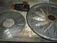
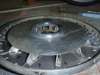
This pic is of a 265mm diameter side plate (magic pie) so the centrifugal effect is potentially better than a 198mm 9C but the inlet holes are a lot more conservative(large reduction in real flow) than Justin's tests
I have been using 12 vanes 20mm high that just clear the phase wires and hub and it has helped temps a bit over just plain holes at high rpm.
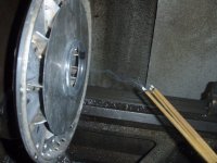
At 480rpm in the lathe there is a noticeable wind off the vanes and tonight just as a last minute try i thought i would cut out a .7mm disk of aluminum to act as a end cap to the vanes more like a industrial type blower and see if it improved air flow
View attachment 5
P4220016.jpg
P4220019.jpg
But it did not seem like any major improvement over standard vane arrangement.
These ventilation mods are good at commuting speeds and is nearly free, efficient and reliable but does near nothing at stall to low speed so for certain riding situations we need active cooling as well.
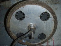
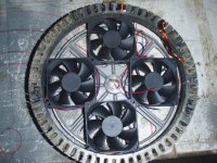
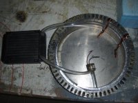
This was used with vanes and vents as a quick and dirty try to see how long the fans would last in a such a hot, rough environment. They are still going after 18 months of jumps, riding through creeks on the beach etc. The thin aluminum sheet is screwed to the stator with a bit of heat paste to try and increase heat loss surface area from the stator.
This was a very large improvement and any time you stop to open a gate, wait for a friend or stop at the traffic lights the temps dropped about 3 times quicker than with the fans off, and heat soak of magnets after a ride was no longer a concern. I use stator temps of 150C as max and turn off the handle bar switch for the fan at 80C. 4 fans offer 46cfm in total. But at very high speed they make little or no difference.
P4220022.jpg
Here are a couple of other options to think about?
P4220023.jpg
P4220021.jpg
Sorry to rabbit on. I am really looking forward to the oil cooled tests and any added losses(more heat load) and curious to see if there is any drop of in torque with magnet temps.
Zappy
 
madmaxNZ said:
Hi Piwhy
I also agree it is too early to go drilling lots of holes just yet.

I went the low Tech easy way of using the oil cooling method which only required one tapped 6mm hole for a bolt and some oil [note: a small breather hole is required thru the bolt; otherwise the oil will be forced past the axel seal when it heats/expands]. The hole should be as close to the axel as possible.The oil level is below the fill hole; about 1/3 of the motor radius (I need to experiment with the optimum level. See photo below. I do a lot of hilly riding on dirt roads/across streams, so air vent holes would let too much debris into my motor.
I use the CA V3 temperature monitor and still get up to my limit of 80degC after extended up hill runs drawing around 20 to 30amps, but there is usually a downhill bit just around the corner to get the motor cooled off again. The same section of hill without the oil was seeing me stop up to 5 times to allow cooling.

I'm looking forward to seeing the comparisons, but will be sticking with the oil method either way since it doesn't require a lot of engineering to the motor. Were I going to go to a lot more effort, I think water cooling is the way to go for ultimate cooling: http://www.endless-sphere.com/forums/viewtopic.php?f=6&t=26029&start=200


Hi madmax,

Oil cooling is an interresting way for our hub heating problems but apparently it seems to be pretty hard to retrofit a hub to obtain a perfect sealed enclosure to prevent oil from leaking outside.
And I didn't removed the disgusting oiled combustion engine from my motorcycle to put oil in my hub again :).

I've thought about my air cooling...
I will probably drill some big holes on the left side as closed as possible from the center plus some smaller ones on the perimeter of both sides covers.
Then I will design an air duct (with a 3d printer), tight-fitted against the left side cover (1mm max between the hub side cover and the edge of the air duct), fixed on my large torque arm, encompassing only the big holes, situated on the center.
This air duct will have one or two large air inputs (50mm), connected to two pipe with their input located in front of my bike.
I hope to focus enough flow into my hub, from the center of the hub, to his perimeter ; if it's not sufficient I will connect a turbine fan on the pipe.
I will draw something in order to interpret easily, that's not eloquent by writting...
 
Back
Top