
You are using an out of date browser. It may not display this or other websites correctly.
You should upgrade or use an alternative browser.
You should upgrade or use an alternative browser.
Definitive Tests on the Heating and Cooling of Hub Motors
- Thread starter justin_le
- Start date
piwhy
100 mW
Merlin said:you will get alot of dirt too in it ;(
1-2 days ago i saw some pictures how many dust(sand) goes inside...
I only drive on asphalted road in city or Parisian suburbs, rarely under rain and never under snow and I plan to fix a fine mesh screen on each holes.
That's should be enough to prevent from dirt going inside, isn't it ? And if that's not enough I can add a filter on air pipes...
John in CR
100 TW
piwhy said:Merlin said:you will get alot of dirt too in it ;(
1-2 days ago i saw some pictures how many dust(sand) goes inside...
I only drive on asphalted road in city or Parisian suburbs, rarely under rain and never under snow and I plan to fix a fine mesh screen on each holes.
That's should be enough to prevent from dirt going inside, isn't it ? And if that's not enough I can add a filter on air pipes...
I too was initially concerned about getting debris in the motor, but over 2 years and no problems and I'm just not concerned any more. Salty water is the only thing I'd worry about, and for that I'd go overkill with a coating and rinse the motor with fresh water after use.
None of my vented motors have had anything more than some road film inside, far less than the thick layer of rust inside most of the sealed motors I've purchase used. I believe the key is getting the perimeter holes at the perimeter, so whatever gets in has a way to flow right out. Zappy rides his off road and through water and mud.
Obviously a good coating on exposed metals in the motor, and mounting it so the hall sensors are at the top, are pretty much mandatory.
I don't think screens in the intake holes is a good idea because it's just too much flow restriction. My planned screen approach that I've found unnecessary is to make a 5" or so ring of plastic, and cover the entire diameter with a screen and a hole just larger than the axle. Fix the ring to the cover sealing the edge with silicone, and fixing the center to the axle seal. Then you end up with a much larger area of screen to flow through and that resistance to flow could easily be offset with a cowling, air dam, or whatever to direct air at the intake.
John
rscamp
1 kW
Just a thought. Since the rotation speed of the hub is so slow, the flowrate generated by radial blades added for form a centrifugal blower is likewise low. There is air travelling past the bike - what about scooping some of this air with a good size inlet? Maybe a stationary one that directs air over or through the hub...
hjns
100 kW
John in CR said:The tail rotor doesn't work very well once there's a fast flow at 90°. That's why it has a tail and rudder. That's also why the tail rotor is outside of the swept area of the main rotor, since the main thrust would render the tail rotor almost useless at low air speeds where it is needed the most for fine control.
Hmm, I guess it depends. There are many helis without any rudder, and just the tail to act as a point of fixation for tail rotor at a 90o angle.

I do agree that the tail rotor is most effective outside the swept area of the main rotor.
This is consistent with my own RC heli experience. I have adjusted many small models, and the main thrust of the main rotor does indeed interfere with the tail rotor's effectiveness. However, even with the tail rotor directly within the swept area of the main rotor, with the main rotor elevated, and the tail shortened to within the reach of the main rotor, the tail rotor is still able to provide enough thrust to counter the contrarotation induced by the main rotor. It is the short leverage of the short tail that then is the main issue, not the variation is air flow.
Therefore, even in situations where there is a large air flow, like the main rotor of a heli, or the speed of an ebike, an active fan at 90o angle can be really functional. I did a lot of bench testing with very small collective pitch helicopters, trying to figure out the best thrust at 1S and 2S and various ratios for motor gear and main gear. I stopped this hobby in favour of my ebike !!!
I am looking forwards to see more results for cover fan configurations and active fans that generate flow inside the hubmotor from inlet to outlet vent holes.
[youtube]vo1R193vfpQ[/youtube]
[youtube]zpfeGupcUns[/youtube]
[youtube]dV8RotBuLXU[/youtube]
speedmd
10 MW
Looks like lots of folks are chomping at the bit for the next posts on the testing to see which ways may be best to explore further.
Open/sealed, wet/dry Me too.
To bad it is such a bitch to weld up all them new air holes so the covers can hold some oil.
Open/sealed, wet/dry
To bad it is such a bitch to weld up all them new air holes so the covers can hold some oil.
John in CR
100 TW
Merlin said:totaly confused which way i should go
can someone tell my where i can buy "new" sidecovers for the 3540?
Why do you think you need "new" side covers? If you already have some big holes in the covers, then it should be easy to modify what you have to make it flow air better. Just add a bunch of small exhaust holes at the extreme perimeter that butt up against the rotor ring retaining lip. I say small because that's the only way to get them at the perimeter. Add some blades, though I'd suggest bending them at about 45° instead of the 90° vanes in the pics above. Do the blades right at the leading edge of your existing big holes (assuming that's what you have and they're near the windings) giving you some adjustability from the outside. If you don't have any holes toward the center you can add some intake there too for an even freer air intake.
That will get you some cooling air flow, but you probably should look at controller settings too. What phase and battery current limits are you running?
speedmd said:Looks like lots of folks are chomping at the bit for the next posts on the testing to see which ways may be best to explore further.
Open/sealed, wet/dry
Hey guys, unfortunately I had to put a pause on this testing process just as it was getting interesting due to some prior project commitments with more imminent deadlines. There is a small chance we'll be able to run one of the oil cooled tests this weekend, but otherwise we'll need to put things on hold for a good 5-6 weeks before things can resume.
-Justin
Marc S.
100 W
justin_le said:Hey guys, unfortunately I had to put a pause on this testing process just as it was getting interesting due to some prior project commitments with more imminent deadlines. There is a small chance we'll be able to run one of the oil cooled tests this weekend, but otherwise we'll need to put things on hold for a good 5-6 weeks before things can resume.
-Justin
Hi Justin,
You will probably testing an oil cooled direct drive hub first to get comparing data to the previous tests...
As far as I'm concerned I'm eagerly waiting for your tests of oil cooled (and lubricated!) geared hub motors.
Thanks for doing this tests!!
Marc
John in CR said:Why do you think you need "new" side covers? If you already have some big holes in the covers, then it should be easy to modify what you have to make it flow air better. Just add a bunch of small exhaust holes at the extreme perimeter that butt up against the rotor ring retaining lip. I say small because that's the only way to get them at the perimeter. Add some blades, though I'd suggest bending them at about 45° instead of the 90° vanes in the pics above. Do the blades right at the leading edge of your existing big holes (assuming that's what you have and they're near the windings) giving you some adjustability from the outside. If you don't have any holes toward the center you can add some intake there too for an even freer air intake.
That will get you some cooling air flow, but you probably should look at controller settings too. What phase and battery current limits are you running?
hey john,
i havent drilled holes yet. thats the problem. i dont know what way i want to go (air/oil)
when i have drilled holes, i cant use oil...but when air coolings not enough, i would give it a try.
(thats the point where i need new covers :lol: )
thats my first year with electro bikes. And i started in winter. There was no PRoblem to drive the 3540 with 5KW on Street.
But i have a large hill behind house where i havfe fun with my dog. now spring has startet and this hill will kill my motor ... sure i can drive with 1-2kw only..but this sucks. iam infected on electro powered bikes
maybe its a problem too that i dont have much tools to "build" something other than holes ;(
speedmd
10 MW
Great! Look forward to seeing the initial results. A small taste should hopefully help make a more interesting layover.justin_le said:speedmd said:Looks like lots of folks are chomping at the bit for the next posts on the testing to see which ways may be best to explore further.
Open/sealed, wet/dry
Hey guys, unfortunately I had to put a pause on this testing process just as it was getting interesting due to some prior project commitments with more imminent deadlines. There is a small chance we'll be able to run one of the oil cooled tests this weekend, but otherwise we'll need to put things on hold for a good 5-6 weeks before things can resume.
-Justin
speedmd
10 MW
Some source for some various size HBN (hexagonal boron nitride) fine powder samples for increasing oils heat transfer.
http://sandblastingabrasives.com/hexagonal-boron-nitride-powder-order-page-781.html
http://www.lowerfriction.com/product-page.php?categoryID=2
Interesting looking stuff.


http://sandblastingabrasives.com/hexagonal-boron-nitride-powder-order-page-781.html
http://www.lowerfriction.com/product-page.php?categoryID=2
Interesting looking stuff.
-dg
1 kW
I hope no-one becomes confused and tries CBN (cubic boron nitride) by mistake. CBN is an extremely hard (equal to diamond) abrasive commonly used in high speed steel grinding where diamond will wear away due to the carbon dissolving into the iron at high temperatures.speedmd said:Some source for some various size HBN (hexagonal boron nitride) fine powder samples for increasing oils heat transfer.
I use a 1.0 micron CBN slurry on balsa wood to strop knives as a final sharpening step. It is quite aggressive even on very hard steel, just a couple light passes make a difference. Diamond would also work for this as it is not a high temp application, but I like the CBN scratch pattern better.
The point being that CBN would probably be worse than unkind to bearings and gears.
speedmd
10 MW
Hi dg
Yes, the name is close. I had the same initial reaction to it. One is very slippery and one not at all. CBN is the correct super abrasive to use on ferrous metals. In grinding wheels it is Great stuff and I use it for grinding many of the hard steels I work with regularly. Never tried the loose abrasive, but benchers (Mold polishers) were just starting to use it opposed to loose diamond on very hard steels some ten-fifteen years back. At hand speeds it is not quite as efficient cutting as diamond, but the surface finish was noted to be more uniform. I included the lattice layout images so no one would confuse the two from this point on.
Yes, the name is close. I had the same initial reaction to it. One is very slippery and one not at all. CBN is the correct super abrasive to use on ferrous metals. In grinding wheels it is Great stuff and I use it for grinding many of the hard steels I work with regularly. Never tried the loose abrasive, but benchers (Mold polishers) were just starting to use it opposed to loose diamond on very hard steels some ten-fifteen years back. At hand speeds it is not quite as efficient cutting as diamond, but the surface finish was noted to be more uniform. I included the lattice layout images so no one would confuse the two from this point on.
Obiwan007
1 kW
So Justin, WAY TO GO!! I did have one question of clarity. I have read thought this thread now several times and some of the terminology is getting me confused. It is difficult to tell from the text and pictures if you have perimeter slots/holes on both or only one side cover. You always mention if you are covering one, both or neither of the intake holes, but do any of your tests have perimeter slot/holes on both sides. My perception of the test with the BEST results is that there were slots on one side plate, intakes open on both sides and straight radial fins on the inside of only one side cover. Is that correct? If so, I wonder what the effect would be with slots on both sides and fins on both sides.
izeman
1 GW
did some testdrive with my oilcooled hs3540 today. see: http://endless-sphere.com/forums/viewtopic.php?f=3&t=38848&start=75#p735403
20min ride on hilly terain. 2.5-3.5kw peaks and wot as much as possible for the first half, then trying to see how long it takes to reach temp limits.
last time i did it w/o oil, i was not able to ride anymore after 10min as temp at the windings (where phase wires and windings are soldered together) reached 120°C.
this time temp was starting to reach 90s at the same time. so ways better.
climbing a quite steep hills where i do 10km/h with my mountain bike (hobby/amateur mbiker), i was doing 30km/h with ~1600w and temp was totally stable at 90°C.
then i set to unlimited (3.5kw) and rode wot for the last 2km uphill. at my house windings had reached 98C. after one minute this was down to 88, then 82,78,75,72 and 70 after 6min. case temp between the spoke holes - so nearest possible to the magnets was 56,55,54,52,51,49 and 48. axle was 30 in the beginning and 33 after 6min.
so i guess i was NEVER even close to some bad temperature. i also think that placing the temp probe directly at the phase/winding is no ideal as there is no leveling. push it hard for a minuted and it will rise to some 100°, and will come down withing a min for 10-15° again. it would be better to take the temp of the stator near the windings i guess.
i probably will raise the temp limiting of the CA-V3 as 90° is too conservative i think. on the other hand i think this will just move the time until limiting some minutes to the future only.
rui_fujino
1 kW
I know some people must have thought about this but has anyone attempted to make a use of peltier?
I think instead of trying to use ambient temperature to cool hub motor, we should be using something which is cold to cool hub motor.
since the hub is designed to spin, we can use the peltier to cool down inside the hub and some sort of air vent to release the hot air outside.
any thoughts?
additional video:
[youtube]3x-wxLEfLEQ[/youtube]
robbie
1 W
- Joined
- Sep 28, 2012
- Messages
- 50
Justin and I are riding down to San Francisco for Maker Faire, and have similar front motors, with thermistors installed. Mine is oil-cooled with ATF and black-anodized side covers and Justin's is sealed with only ambient cooling on the silver side-covers. Once we get the CA's hooked up to monitor the temperature we'll get a chance to compare the temperatures between our two setups - though with our different total vehicle weights, aerodynamic profiles and power usage the comparison may not be that accurate.
GCinDC
100 MW
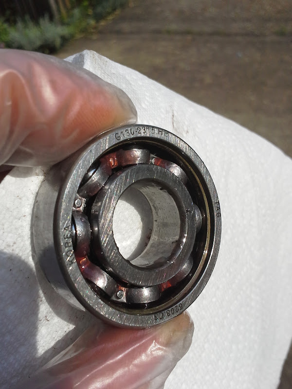
nice work. fyi: i realized too late that my bearing were only rated to 100C and the bearing seals failed after too many times hitting 120C (seal removed showing atf in bearing) from here:izeman said:did some testdrive with my oilcooled hs3540 today....at my house windings had reached 98C.
h0tr0d
1 kW
- Joined
- Apr 28, 2012
- Messages
- 460
GCinDC said:nice work. fyi: i realized too late that my bearing were only rated to 100C and the bearing seals failed after too many times hitting 120C (seal removed showing atf in bearing) from here:izeman said:did some testdrive with my oilcooled hs3540 today....at my house windings had reached 98C.
Great bearings and cheap!
http://www.ebay.co.uk/itm/E26203ZZC3-SKF-Energy-Efficient-Bearings-17x40x12mm-E2-6203-ZZ-C3-SKF-/161008943959?pt=LH_DefaultDomain_3&hash=item257ce18357
izeman
1 GW
Those seem to be the same already installed in my motor. Though I guess mine are not genuine SKFh0tr0d said:GCinDC said:nice work. fyi: i realized too late that my bearing were only rated to 100C and the bearing seals failed after too many times hitting 120C (seal removed showing atf in bearing) from here:izeman said:did some testdrive with my oilcooled hs3540 today....at my house windings had reached 98C.
Great bearings and cheap!
http://www.ebay.co.uk/itm/E26203ZZC3-SKF-Energy-Efficient-Bearings-17x40x12mm-E2-6203-ZZ-C3-SKF-/161008943959?pt=LH_DefaultDomain_3&hash=item257ce18357
120C at the bearings? Did you have no temp probe installed? Windings must be cooked already at those temps.
pendragon8000
100 kW
i have thought about it...rui_fujino said:I know some people must have thought about this but has anyone attempted to make a use of peltier?
I think instead of trying to use ambient temperature to cool hub motor, we should be using something which is cold to cool hub motor.
since the hub is designed to spin, we can use the peltier to cool down inside the hub and some sort of air vent to release the hot air outside.
any thoughts?
additional video:
[youtube]3x-wxLEfLEQ[/youtube]
WHAT IS A PELTIER? : basically a heat pump that runs off electricity with no moviing pars, exploiting a phenomenon that occurs with 2 different metals layered up with electricity passing through one side gets hot one gets cold, typically 20ºC deference but can be stacked in series. also worth noting electricity can be generated by heating one side and heatsink to ambiant the other side. and if polarity is switched the other side gets hot instead..
i think a bunch of peltiers say 4 on each side of the stator would have a prety good effect. basicaly accelerating the inevitable heat of the stator going to the sidfe plate and to ambiant or if its drilled then from stator to air/side plate. they are a bit inefficient but say 8 x 60w moduels = 480watts of peltier. personaly i wouldnt bother trying it unless i went for some serious business aproch like that..
also another thing to consider is just old fashioned heatsink on the stator. i mean they do work, thats been proven, why not just jam as many as can fit on the stator wthout touching the rotor? im sure the cooling effect would be significant. think about our controllers with that heatsink shell dispersing heat as air passes over it...
izeman
1 GW
Sorry, but peltiers are nonsense. Using electric energy to remove heat produced by too much energy pumped into the motor just seems wrong.
Putting heat sinks on the hub between the spokes would make sense. They are moving in the air and would be cooled quite well.
Putting heat sinks on the hub between the spokes would make sense. They are moving in the air and would be cooled quite well.
Similar threads
- Replies
- 19
- Views
- 3,087
- Replies
- 17
- Views
- 2,102
- Replies
- 25
- Views
- 6,836
- Replies
- 63
- Views
- 7,896