eBike Master Switch Design

The Controller's Capacitor Bank

There is a lot of energy stored in the controller's cap bank. If this Master Switch turns off instantly, the controller cap bank is going to slowly decay over a period of time that can be quite long. That can cause confusion about what appears the Master Switch is or is not doing. :)
 
Alan B said:
The Controller's Capacitor Bank

There is a lot of energy stored in the controller's cap bank. If this Master Switch turns off instantly, the controller cap bank is going to slowly decay over a period of time that can be quite long. That can cause confusion about what appears the Master Switch is or is not doing. :)

sure. the controller's caps are feeding back into the circuit keeping it open longer than you want. but if this happens we can't speak of a "instant off" situation, can we? will this still work as an "emergency" power cut?
 
izeman said:
Alan B said:
The Controller's Capacitor Bank

There is a lot of energy stored in the controller's cap bank. If this Master Switch turns off instantly, the controller cap bank is going to slowly decay over a period of time that can be quite long. That can cause confusion about what appears the Master Switch is or is not doing. :)
sure. the controller's caps are feeding back into the circuit keeping it open longer than you want. but if this happens we can't speak of a "instant off" situation, can we? will this still work as an "emergency" power cut?

the display on my bike goes out only in 10sec or more but its no problem for me... with some drain on my dc/dc converter its out in about 3 sec (i leave the light always on).
FET turn off is INSTANT so i think there will be no problem in an emergency power off..
Maybe built in some big resistor on drain side to discharge caps?
 
How about using the master switch to trigger an SCR on the controller side to deliberately short out the controller caps? It would be something like the OVP on various types of switching PSUs.
 
It is not clear to me that we have a requirement to drain the controller caps, that's not the master switch's purpose. Extra circuitry could be added but it goes way beyond what is needed to accomplish the stated requirements of the master switch, and adds to cost, complexity and size. If this extra circuit ever gets triggered falsely it will probably be destroyed or at least waste power.

If you want the controller to go off immediately then drop the control power input to the controller at the same time you drop power to the master switch's control input, as recommended in the earlier system diagrams in this thread. The bleeder resistors on the controller will drain the caps soon enough.

In an emergency off scenario the caps would drain out nearly instantly if there was a load, so the system will shut off mechanical output power pretty much immediately.
 
you are right alan. there is NO need to drain the caps. it's only a "problem" when testing the circuit with a controller on the bench. on the bike with some minimal load the caps would be instantly drained to zero when power is cut.

maybe someone who did order a bigger supply of those TO-92 FETs (TP2104N3-G or ZVP4105A) could send me one. please PM me and i will paypal you for p&p.
 
Used the meter with locked ranged and observed voltage at the controller. Turns out the voltage changes are sufficiently slow and small enough in magnitude that the bargraph probably wasn't necessary. With control voltage on, voltage at the controller is about 70 v. With control off, voltage rapidly falls to about 10 v and then oscillates between about 9.9 and 10.9 v with a periodicity observed for the flashing of the cycle analyst screen.

Rich
 
Interesting data, glad you did that.

Something is going on there to charge the caps up again, is there some other path for current around the master switch? It is very important to avoid connecting anything to battery minus except the master switch. Other loads should get their negative connection from the controller side of the master switch.

It could be that the master switch is leaking a small current. This might happen if there is damage to any of the power FETs, or leakage in the nonpolar delay capacitors.

Something's not right.
 
It is certainly possible that I damaged something while soldering things in place. I initially had trouble with the 4110 fets because of my underpowered soldering iron, maybe I damaged one or more of them?

Rich
 
Alan B said:
It is not clear to me that we have a requirement to drain the controller caps, that's not the master switch's purpose. Extra circuitry could be added but it goes way beyond what is needed to accomplish the stated requirements of the master switch, and adds to cost, complexity and size. If this extra circuit ever gets triggered falsely it will probably be destroyed or at least waste power.
sorry--I do best solving problems that don't exist. :lol: :oops:
 
No need to apologize AmberWolf, thanks for reading and making suggestions, and cleaning all the junk out of the forums! We are in your debt.

At first I was worried that there was a problem with the circuit, now it begins to look more like there is something else going on with Rich's test board. Could be a flakey FET, or some other leakage path for current. It would not take much.
 
Measure the voltage between gate-source (two outer pins) when it's doing that oscillation thing. If there is zero gate voltage, then you have some kind of path bypassing things or a FET is leaky. If you have something around 2v, then the problem is on the gate drive and the FETs are good.
 
Alan B said:
Something is going on there to charge the caps up again, is there some other path for current around the master switch? It is very important to avoid connecting anything to battery minus except the master switch. Other loads should get their negative connection from the controller side of the master switch.

thx for this important Info. sounds reasonable.
 
Measured the voltage between the gate and source for the 4110 FETs when the control power is "off" which is the condition where my build of the board has a voltage oscillation at the output. Under these conditions the voltage between the gate and source for all 4 main FETS seemed to oscillate between about +0.5 and -0.5V.

Rich
 
That's not enough to turn the FETs on, so the current is either leaking through one of the FETs or coming along some other parallel path. If you disconnect the switch but leave everything else as is, does the controller voltage go to zero then?

The FETs are sensitive to static discharge, and to overheating. Unfortunately hard to tell which FET is bad. :(
 
Hi Alan,

I am wondering if your design can be adapted to use its own switching power supply like a 9v. I have zero ability in reading how this board works (though I am pretty sure I could assemble it) so no idea if this is feasible due to current draw on the separate cell etc. Maybe making it adaptable so that the pack voltage + can switch it on and a jumper for the pack - or connecting a separate battery, so it is up to the end user to decide which option.

I couldnt care less if the 9v had to be replaced yearly or even bi yearly.....weekly might be another case though.

Rodger
 
Alan B said:
It doesn't need a separate supply, it works from battery voltage to turn on, and open circuit turns off.

yes I understand this. But this ties it to the - side of the load. This is why I liked methods solution, because it could go anywhere. If it had its own power source wouldn't that allow it to go else where? Also in the case of a not so waterproof switch on the handle bars, I would much prefer to feel a 9v short to my thumb than 100v. If its not possible without serious redesign/addition etc it is probably not worth the effort, I was just curious.
 
It could be triggered by 9V with some changes to resistor values. Then it could be in the + lead. But understand that it would be sitting at B+ voltage then. If you want to have only low voltage on the handlebars you could use an 9V driving an optical isolator, and have that drive the switch. I've seen 150V output optical isolator chips that should do nicely.
 
rodgah said:
yes I understand this. But this ties it to the - side of the load. This is why I liked methods solution, because it could go anywhere. If it had its own power source wouldn't that allow it to go else where? Also in the case of a not so waterproof switch on the handle bars, I would much prefer to feel a 9v short to my thumb than 100v. If its not possible without serious redesign/addition etc it is probably not worth the effort, I was just curious.

battery voltage at the keyswitch is indeed not good. I also bother about what will happen if some water get in a non-waterproof keyswitch circuit? I think it will turn on the masterswitch or short circuit..
 
madin88 said:
rodgah said:
yes I understand this. But this ties it to the - side of the load. This is why I liked methods solution, because it could go anywhere. If it had its own power source wouldn't that allow it to go else where? Also in the case of a not so waterproof switch on the handle bars, I would much prefer to feel a 9v short to my thumb than 100v. If its not possible without serious redesign/addition etc it is probably not worth the effort, I was just curious.

battery voltage at the keyswitch is indeed not good. I also bother about what will happen if some water get in a non-waterproof keyswitch circuit? I think it will turn on the masterswitch or short circuit..
what's the difference between battery voltage at the switch or an external power supply? the result when it shortens is the same: the controller is turned on. only difference in your case may be that water may short circuit a 100v+ circuit easier then a small voltage one (like my 44v). you may even disperse the switch into a glass of water and nothing would happen.
 
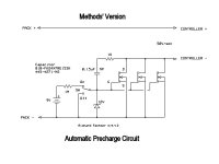
I drew this one up a while ago for Methods. Since it's battery powered, it could actually be on either the positive or negative side. A standard 9v battery should last for many years as there virtually zero drain on it.

Automatic Precharge 3c schematic (Methods').jpg
 
Just a couple of notes relating to the above circuit:

The handlebar run/stop switches I have (and have seen) are SPST so not compatible with this circuit.

There's still pack+ or pack- at the switch, if they want isolation a relay or optocoupler would be required. In high voltage systems isolation is sometimes required, or at least considered to be a good thing.

If the 9V battery gets low the FETs could be destroyed when they become unsaturated.

The FET gates are unterminated when the battery is disconnected and the switch is on, and while the switch is swinging between contacts. FET gates are very sensitive and easy to destroy.
 
Back
Top