Eric's Project #002

#420 chain will fit on a bicycle sprocket? i know the pitch is the same but isn't the chain too wide for the sprocket? seems like it would fall off easily or wear really fast.
 
dirty_d said:
#420 chain will fit on a bicycle sprocket? i know the pitch is the same but isn't the chain too wide for the sprocket? seems like it would fall off easily or wear really fast.

It should work. The BMX sized chain is 1/8" in width. The first derailler chains were 3/32". The newer chains for the 8,9,10 speeds are thinner.

The easiest thing to do is grind the #420 sprocket down to make it thin enough to fit. Using a hand held grinder you simply connect the motor to the batteries (to make the sprocket spin) and then just grind the sprocket down as it spins. It's like having your own lathe. :)

I'll be welding my 18 tooth onto mine and adding a spacer at the same time in order to bring the sprocket as close to the motor as possible. If that doesn't work... you know you can buy any sprocket you want from here:

http://www.mcmaster.com

Try:

"ANSI 40 Roller Chain Sprockets"
 
dirty_d said:
#420 chain will fit on a bicycle sprocket? i know the pitch is the same but isn't the chain too wide for the sprocket? seems like it would fall off easily or wear really fast.


Yes, 420 chain fits perfectly:

http://www.gizmology.net/sprockets.htm

The chain is a little wider than the sprocket.

Actually I think it would be more likely to stay on it the chain is a little wider. I think one of the most important things is having the teeth of the sprockets taper (become thinner) at the points. This makes it so the edges of the chain can never touch the tips of the teeth, causing the chain to come off. Also, I'm using a 9 tooth and 17 tooth sprocket which means that the chain is tightly packed onto the teeth. Bigger sprockets have aa better chance to derail (in my opinion).

The sprockets I don't like are the flat sprockets made for the narrow (10 speed type) chain. They have no tapering so the chain isn't forced to center itself.


The7 said:
Seems it is an bushed motor !?

Yes, its brushed. ITs cheap. It has a cheap sounding whine. And it only ratied at 600 watts. I want to run about 25 amps @ 48v. That is about 1200 watts, or roughly double what this thing can handle.

The thing I like about this motor is that its a gearmotor. I wish I could find a brushless, super efficient (90%) gearmotor rated at 1000 watts.

I love the powerpack one that fetcher uses, and at some point I may convert over, but its a bit of a hassle. Also, I don't like that it spins at 3700 rpms. I hate having to reduce the gears to managable speeds.
 
Latest Plans


These are my latest blueprints for my scooter. This is the third time I've made them becasue the houskeeper threw away all the little scraps of paper laying around, and the dogs got my second set.


You may be asking, "How the hell is he going to make a scooter from that crappy drawing?" And I don't blame you.

But really I don't think it will run into too many problems. I think the key is to assemble everything in the right order. I've found that I've been able to design individual part that I know will be o.k., then it tends to "force" the other parts to fall into place.

Right now I'm planning to assemble it in this order:

1) Attach the back forks to the battery box allowing a little bit of clearance for the motor. This will force the shocks to be positioned in a certain place.

2) Then I will attach the diagnal piece that attaches to the top of the shocks and runs over the motor. The angle will be determined by allowing 1 inch clearance from the motor. It doesn't matter the exact angle.

3) Attach the horizontal piece that runs from the top of the shocks to underneath the seat. Again, angles and measurements aren't important.

4) position the front forks where I want them (perhaps 28 inches from the seat) and at a good angle, and connect with aluminum pieces.

Also, Handlebars can compensate for lots of issues.

I'll position foot pegs to whatever is comfortable.

If all goes well, my wheel base will be between 46-49 inches. The seat will be 27-29 inches from the handlebars.

Wish me luck.


Attachments

  • DSCN0477.JPG
    DSCN0477.JPG
    27.6 KB · Views: 4,026

Bits of Progress


I made the brackets that will hold the shocks today. There's an "L" shaped piece and a straight piece that will be welded to the back forks (see pics)

I cut the head tube off the Mongoose bike I bought, and abraded the paint off. It would be nice to get a new tubs, but I don't know the size of it. I'm already ordering the tube that the seatpost will slide into tomorrow, so it would be easy to add to my order. Does anyone know the standard sizes of the seatpost and head tube?


I'm going to call this place tomorrow:

http://www.fairing.com/bicycle_frame_depot.asp?subcat=a76

I cut the pieces to make the piece that goes from the top of the shocks over the motor (diagonally). I'll have it welded tomorrow.


Attachments

  • DSCN0482.JPG
    DSCN0482.JPG
    31 KB · Views: 4,018
  • DSCN0481.JPG
    DSCN0481.JPG
    44.3 KB · Views: 4,018
  • DSCN0478.JPG
    DSCN0478.JPG
    30.5 KB · Views: 4,017
  • DSCN0479.JPG
    DSCN0479.JPG
    61.2 KB · Views: 4,016
  • DSCN0480.JPG
    DSCN0480.JPG
    35.6 KB · Views: 4,019
More Welding Done
I brought the top and bottom of my battery box to the welder to be welded together. The diagonal pieces will hold the seatpost tube.

This is what it looked like after it was welded.
 

Attachments

  • DSCN0488.JPG
    DSCN0488.JPG
    56.1 KB · Views: 3,980
Tube For Pivot point Welded

I'm going to use an aluminum tube connecting both sides of my back forks together as a pivot point (see pic) a 1/2 bolt will be connected to the back of the battery box and go through the tube. The bolt will be anchored to the battery box so the back end should pivot when I go over a bump and the shocks are compressed.
 

Attachments

  • DSCN0487.JPG
    DSCN0487.JPG
    40.8 KB · Views: 3,974
  • DSCN0484.JPG
    DSCN0484.JPG
    43.1 KB · Views: 3,969
  • DSCN0490.JPG
    DSCN0490.JPG
    50.5 KB · Views: 3,973
Now Its Starting to Look Like Something

I cut the excess from the back forks and the battery box so the pieces can fit tohgether. I still need to drill a hole for the bolt to connect them. I'm planning on reinforcing that spot by adding a small 1/8 inch thick plate to the exterior so the bolt has no chance of breaking the pivot point. The total thickness of the aluminum will be 5/16th of an inch at that point (3/16 battery box + 1/8 inch plate)

Also, I had the bracket for the disc brake welded on.
 

Attachments

  • DSCN0489.JPG
    DSCN0489.JPG
    41 KB · Views: 3,974
  • DSCN0492.JPG
    DSCN0492.JPG
    55.1 KB · Views: 3,979
  • DSCN0491.JPG
    DSCN0491.JPG
    54.3 KB · Views: 3,976
you probably wont die... just be horribly maimed. nah, they look pretty crappy butt that doesn't necessarily mean they arn't strong. it looks like he dipped the tungsten into the aluminum in some places where its black but i doubt it will be any problem.
 
If you can weld the backside of some of the joints, that would help. Just a few stitches here and there can make a big difference.

Also, if you're paying good money (ie. more than a case of beer) for aluminum welding, you should be getting something that looks like this:

 
Welding aluminum is pretty difficult and you need a $2000+ machine to do it right. You should see the machine this guy uses. It's about 4 feet tall and cranks out 300 amps. It has water cooling for the tip.

There are a couple of black spots, but most of the welds where shiny when he was finished. He took a long time to make the welds. I.e. the bottom of the battery tray took him 20 minutes and he ran the machine a lot.

I think I over-engineered this thing. If I had to do it over again, I'd make it lighter. I think it will be rediculously strong.
 
Yea those are really nice looking welds, fetcher. My guy makes it look like that, perhaps a bit less consistent, but then he sands them down. You can see both a few pics up.

I'm going to add tread plate to the outside. That will add a LOT of strength too.
 
Beagle123 said:
Also, I'm using a 9 tooth and 17 tooth sprocket which means that the chain is tightly packed onto the teeth.

Smaller sprockets increase the amount of force that each tooth has to carry. This translates into more friction and that means lower efficiency and more wear.

On bicycles it's a "known truth" (in the bicycle world) that the smallest gear is less efficient. (add an extra 5% to 10% in losses)

:arrow: Why not go:

18 front / 34 rear

...the gear ratio will be the same, but the frictional losses will be less.

:arrow: I'm using the same motor and I'll be using

18 front / 43 rear

...which combined with the 8 speed Sturmey Archer hub covers what I need as far as hills and top speed. (10% slope and 50 mph top speed)
 
That's a good idea, I'll consider that change later. It will involve welding onto my front sprocket, and finding a way to have 34 teeth on the back. Also, I'd like to see my results with those ratios before welding etc.
 
Another Day Another Jig...


I made a jig to atach the head tube to the battery box. Its basicly a piece of plywood cut to the width of the battery box. I secured the battery box to the jig and put two lag screws about 18 inches in front of the battery box to represent the position of the front axle of the bike. Then I put the head tube over the forks and propped them up with a 2X4.

With the battery box and forks secured, I started trying to make pieces that run from the corners of the battery box to the head tube. This is turning out to be a bit of work. I stopped today because I didn't want to be doing tedious work when I'm tired. I can make mistakes.


Attachments

  • DSCN0493.JPG
    DSCN0493.JPG
    48.5 KB · Views: 3,874


Making each piece individually is really difficult. Its hard to get each piece square to each other and to the battery box especially when they're floating in space.

Tying two pieces together makes the job much easier.

I sandwiched two pieces between two pieces of plywood using sheetrock screws. Its much easier to align when its one big piece. The first welding job will be to join these two pieces together at the top, then position them in the frame.

If anyone is planning a project like this, my advise is: use jigs whenever possible


I hope you have plans to surround your head tube with lot's of extra sheet aluminum for extra bracing. I really don't like the extreme angle that the tubes approach the head tube. You do realize that assuming the head tube survives the pounding it will take that the main area of flex will be in those tubes dropping down to the floor of the bike. It's one thing to go "in the middle" and have the frame go directly from the rear to the front (like mine and dirty d's projects) but to go "below the middle" means that the inherent geometric strength is working against you.

I'm just being cautious about this... the design of a scooter is really not mechanically all that great. The "double diamond" has a lot going for it because it's geometric configuration deals with stress extremely well. The "delta box" design with the "in the middle" frame uses the "shortest path means strongest result" concept. But the "below the middle" scooter frame has no natural geometric advantages.

:?: Why did you settle on this? Was it because your current bike is a scooter and so you just copied the dimensions?
 
Hi safe:

Yes I plan to use aluminum tread plate to cover the sides of the whole thing. I'm planning to use slightly thicker tread plate on the neck of the bike just for the reasons you mentioned. So there will be 4 angle pieces welded onto the head tube, then there will be a sheet of treadplate weldes to the head tube as well. The tread plate should add huge amounts of strength to the bike. For most of the bike, its overkill, but on the neck it will really help.

I chose the design because I like how it looks and its comfortable. I don't really care about going fast. I'm more concerned with how it handles hills. I know the aero-dynamics will be poor becasue it's an upright bike, but when you go up hills, usually you have to go much slower, so wind resistance is less of a factor. I beleive that we all have bikes that perform very very well on flat land. The real measure for me is how they handle hills.

My current bike goes about 10mph up steep hills. If I can get this one to go 15mph, I'll be very happy.

COnsult my "before" picture:


Attachments

  • DSCN0445.JPG
    DSCN0445.JPG
    43.8 KB · Views: 3,312
I'm happy to be the only one here so far that is really onto the "Road Racer" concept. To each his own. (sounds like you have plans for lot's of bracing on this one which is good)
 
Bracket For Shocks Welded, Back Forks Attached to Battery Box

First of all, thanks safe, and thanks for all your help. You've helped me a great deal with my project, including giving me the inspiration to tackle framebuilding.


The brackets that hold the shocks look really good. Again I over-engineered it. They're 3/16 in aluminum with welds everywhere.


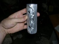
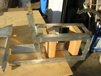
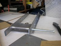
I'm using a hinge setup for the pivot point between the body of the bike and the back end. Its just a 1/2 X 7 1/2 inch bolt that connects the sides of the battery box together. The back end has an aluminum tube that the bolt fits into perfectly. There's a steel washer on each side. When the bolt is tightened it make the back end fit snugly between the washers. There's a bit of friction, but not much.


I welded little squares of a3/16 inch aluminum over the spots where the bolts penetrate so there's no chance of this point breaking. This is a critical spot. THe total thickness of the metal is 3/8 inch. Should be fine.

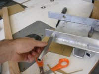
I spent about two hours checking and re-checking the locations of the holes to attach the back of the battery box. It was difficult because there was no way to put the forks in place and mark for holes because they would be covered by the tabs on the back of the battery box. I had to drill a hole on one side, then align the opposite hole buy using a framing square to transfer the point across to the other side. When all was done, the back of the forks were off by perhaps 1/8th of an inch. Actually I think that's pretty good because every minute fraction you're off on the hinge end is magnified by about 3 times on the back. I did a little bit of filing on the holes to even it out, but I think its fine. In fact, I wouldn't be suprised if it was perfect when the wheel is put in.


Attachments

  • DSCN0505.JPG
    DSCN0505.JPG
    41.7 KB · Views: 3,262
  • DSCN0504.JPG
    DSCN0504.JPG
    40.8 KB · Views: 3,263
  • DSCN0507.JPG
    DSCN0507.JPG
    40.2 KB · Views: 3,262
  • DSCN0508.JPG
    DSCN0508.JPG
    31.4 KB · Views: 3,262
Back
Top