Giant DH Team, Cromotor, 18fet Lyen, 111v Lipo

The main battery lead is currently set to 50A and the phase to 65A.... yea.. quite a bit lower then it could be :(.

To be honest.. I'm quite a noob when it comes to this electrical stuff.

I pop'd the FET running at 65A main leads 125A phase with a 30s configuration. I happened under a 75% throttle application up a slight hill from a dead stop. I had previously over heated the controller... I think this might have contributed to the fact it pop'd.

I'll be slowly increasing the phase amps as I get more comfortable that my replaced FETs are good!
 
binlagin said:
The main battery lead is currently set to 50A and the phase to 65A.... yea.. quite a bit lower then it could be :(.

To be honest.. I'm quite a noob when it comes to this electrical stuff.

I pop'd the FET running at 65A main leads 125A phase with a 30s configuration. I happened under a 75% throttle application up a slight hill from a dead stop. I had previously over heated the controller... I think this might have contributed to the fact it pop'd.

I'll be slowly increasing the phase amps as I get more comfortable that my replaced FETs are good!

The 18fet 4115 ll not be able to hold 65a main without mods... but i think you can safely run it at 45a main 115a phase.
Either way, with 50a main you can reach over 70kmh easily, just not as fast because of phase amps are too low.
If you must use 150v fets your best bet will be a stock 24fet or a heavily modded 18fet like the ones steveo does.
 
What is the big difference between a main lead and a phase lead? I understand that one goes to the controller, the other to the motor... but why/how can i output a greater amperage to the phase but have less amp's feeding the system?

Is it because the phases "pulse" over the, green, yellow and blue leads allowing enough time to up sufficient energy to burst at a higher amperage?

I will give that configuration a shot tonight!
 
I agree, you should be fine at 115A phase and 50A battery, but at this point it's really better to drop the voltage down since the extra volts really aren't doing much for you since you will always be in PWM which is OK as long as you are on the high side close to full on.

You may have seen that I have run 105A battery and 130A phase several times with the mods done, but please don't try these levels on any wheel size larger than 20" even if you mod the controller the same way I did. Now that I'm commuting on the bike I have mine limited to 110A phase and 70A battery so it's not so wheelie prone and easier to ride, but it still has a top speed of 55mph. You might be better off going to a 100V FET controller and dropping down to 24S if you are 24" or 26" wheels because it's going to be easier on the controller.

Don't forget, running high speeds drains your battery fast. While my bike is capable of way to fast speeds it doesn't get ridden at high speed for very long at all. I'm normally on speed setting #2 which is 70% throttle and limits me to 40mph max and I switch between #1 25mph max and #2 40mph max pretty often depending on where I'm riding. My #3 setting only comes into play if I'm forced into high traffic area where I feel safer riding as a motor cycle and need the power or just having a little fun.

Post your setup and I can probably make a recommendation on what to do based on experience. Personally I won't run more than 100V on big wheel setups, it's just too hard on controllers and I dislike breaking stuff because I hate fixing it.
 
binlagin said:
What is the big difference between a main lead and a phase lead? I understand that one goes to the controller, the other to the motor... but why/how can i output a greater amperage to the phase but have less amp's feeding the system?

Is it because the phases "pulse" over the, green, yellow and blue leads allowing enough time to up sufficient energy to burst at a higher amperage?

I will give that configuration a shot tonight!

Im not eletronically gifted too, but based on my observation I think that when you alow a phase current to be 2.5 times as big as your main current what the controller does is to module the wave to have much higher current and much less tension.
So when you are launching you motor is actually feed with roughly 40v 100amps and not 111v 40a that you have coming from the battery.

Someone else mind to elaborate?
 
Update:

Got some good progress over the past week. I commuted to work all week long at 50amps at the battery and 90amps at the phase. My controller handled it all week with no sweat. I bump it up a bit.. but my battery useage was leaving me aabout 15-25% left at the end of my daily commute... so maybe I'll leave it alone.

I've build a nice wrap made out of a pad that goes under a horse saddle, to contain the batteries and wires. No pictures of this yet.. but I will get some!

Unfortunately last-night I was ripping around around 1am with poor lighting and I hit pot hole at 60km/h. I got a small dent in my rim... nothing major, but unfortunately I lost power immediately after it happened. I tried reapplying the throttle but it kinda just "burped" and lurched forward, then it eventually stopped lurching forward at all. I immediately though I damaged my phase cables or hall sensors.

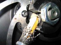
Upon further inspection... I was correct... looks like I'll be looking for a gear puller tomorrow around the city. My disc brake severed my hall sensors and possibly my phase wires:

cut_wires_small.jpg

FULL RESOLUTION: http://www.bgraham.ca/ebike/photos/cut_wires.jpg

Anyone got some good tips for working on replacing hall sensor cables and/or phase wiring? While I have the motor case open, I guess I should look at getting some anti-rust proofing on the coils aswell.

I feel like I'm learning alot... but I only really learn after destroying something. Oh well... I guess that's 1/2 the fun with building your own machine!
 
I find it very hard to understand how did you end up cutting the wires due to a broke rim with theses gigantic torque arms, the only thing I can tell looking at it, its that you need more space between the TA and the disk bolts.
Either way, you are really going to need a gear puller and be careful to no hurt your fingers also some meters of 10-11g silicon wires for the phases and 24-26g silicon wires for sensors will probably be needed. I ll snap a picture of my torque arm for you to see in a couple minutes.
I think 45-50a is the ticket for your controller, now raise the current even further if the bicycle is still safe to ride.

I did burn and broke a lot of stuff before but you ll notice that the failure rate decreases with time, just always overbuild coz broken bones are a real pain. :shock:
 
I've found that there isn't exactly alot of room for the phase, and hall connectors with my dropout and disc combination.

I had to fix a pinch flat yesterday so I had to put off my motor. I normally have a zip tie holding the phase cables down away from the disc of the brake but I forgot to put it back on after fixing the flat. I didn't destroy my rim... but the bump probably knocked the phase wires in the path of the disc and they got chopped.

I hope canadian tire carries gear pullers!
 
binlagin said:
I've found that there isn't exactly alot of room for the phase, and hall connectors with my dropout and disc combination.

I had to fix a pinch flat yesterday so I had to put off my motor. I normally have a zip tie holding the phase cables down away from the disc of the brake but I forgot to put it back on after fixing the flat. I didn't destroy my rim... but the bump probably knocked the phase wires in the path of the disc and they got chopped.

I hope canadian tire carries gear pullers!

I also noticed the wiring can get a bit tight with some discs. What you can do is grind down the eylets on the disc just a little and then I found using heat shrink or a stainless zip tie or both works to keep the wires held nicely in place with no worries of them falling into the path of the disc. It seems to vary a bit form disc to disc how much clearance there is, but it is a tight fit no matter what. I've had zero issues with mine but when I installed the disc saw it could be an issue if the wires are not secured well. I don't trust plastic zip ties, so many junky ones just break. Need some high quality, strong and flexible ones. Got some here that are so brittle you can break them in your hands, total garbage.
 
So I've been successfully been able to open my hub motor and make the necessary repairs to the wiring.

My green phase was slightly knicked and the green and red HAL sensor cables where severed. I soldered everything back together and made some extra clearance for the wiring on the axel.

Good idea with the medal pipe clamp... I might actually have one kicking around.

Now how do I get the motor back together? The coils now keep snapping to the magnets on the rim. Is there any tricks? I've tried the way this guy does it (http://www.youtube.com/watch?v=lkGgAWHSayU), but I'm not able to close the casing up enough to put the side cover screws on. Anyone have some tips?
 
Errr.... Crusoe left his acct logged in on my PC!!! Oops

... My question from above still stands!
 
crusoe said:
Now how do I get the motor back together? The coils now keep snapping to the magnets on the rim. Is there any tricks? I've tried the way this guy does it (http://www.youtube.com/watch?v=lkGgAWHSayU), but I'm not able to close the casing up enough to put the side cover screws on. Anyone have some tips?

I watched Hal9000v2.0 do it with some special tools in his garage after he told me it's very bad to let them just snap in as they could chip a magnet. Those special tools were rolls of tape of different thickness LOL. It works awesome and lets you line everything up before the final snap. He used duct tape, masking tape and electrical tape I believe. Had the motor back together in about 30 seconds.

As for putting the screws in, once the case is aligned right, you need to work in a pattern. You can usually see the stator is to one side so put a screw in on that side first and just snug it, the do the ones next to it and the stator will probably pop over to that side. Then just put the other screws in and start tightening them down a few turns each at a time until it's tight. That's how I've done it, but don't try to fight the magnets with just one screw, you will strip it for sure! Go slow, try to keep it even and everything should go fine.

You also want to make sure the magnet ring and covers are put back together into the same position as when taken apart.
 
So I ran into some more problems last night, leaving me feeling defeated... but I won't give up! I'll figure this out eventually.

I put together my hub as Zombiess mentioned in the post above... everything seemed to be going well. I put the motor back into the drop outs, but I accidently forgot a spacer and ended up cutting all the hall sensor cables again, @#$@!! So, I go back downstairs pull apart the motor and make the repairs. I put the motor back together and ensure everything is clear of the brake disc. I wire everything up, connect the batteries, turn on the CA and twist the throttle... no go :(

I imagine I damaged the hall sensors by shorting it out with the 5v line or possibly one of the phase cables?

Maybe i should invest in one of the ebike testing computers?
 
Try to pedal first, then give it a little bit of throttle (but not a lot) and it should move but really rough. Your problems are then 1. blown FETs (unlikely unless you shorted to phase wires), 2. disconnected phase or hall wire (done this game a few times), 3. bad hall (get ready for fun). I'm guessing you have a bad hall sensor based on your mentioned failure.

I think if you have a blown hall sensor and flip the bike upside down and spin the rear wheel with the crank the CA won't register your speed.

Any time you have a phase wire and a hall wire possibly short you absolutely have to check the hall sensors before you assemble it again. It can be done with a strong magnet and a volt meter. A scope is of course the best, but a volt meter and slowly moving the magnet around the hall sensor (they have a very narrow range) with +5v and ground connected should output about 4.6V when you get the magnet just right. Otherwise you end up in the situation you are in now... one I've been in myself and frustrated as all hell. Luckily this was on my 9C 2806 which was a bit easier to work on in some ways (magnets have much less pull making separation easier, but new 12 gauge wires through the axle a total PITMFA, hint PITM = pain in the mother).

Sorry that you have to pull it apart again, but you are now almost an expert on hub motor repairs. I went through almost the exact same thing you did and was frustrated as hell.

If a hall is bad and it most likely is, the replacement is Honeywell SS411A DigiKey 480-2000-ND. If you don't have any other parts to order just let me know and I'll stick three spares I have in an envelope and mail them to you. Don't know where you live, but if you are in the USA it shouldn't take long. Outside the USA it might be faster to just order them from a mail order electronics supplier and what ever other stuff you might want or think you'll need. I ordered 10 of them since they were only $2.06 each. Glad I had spared because during my learning process on my 9C I managed to break 2 of them on install by trying to force them in... oops.

The hardest part about replacing the halls is getting the old ones out and making sure the hole is clear of debris so the new ones slide in easily. I almost always break the old one and end up chipping / scraping it out with a small screw driver and then install the new ones with silicone RTV but you must let it dry so they stay in position. It's critical that they absolutely stay all the way in when you put the circuit board back on and zip tie it down.

Hope this helps some, I've been exactly where you are and it's so frustrating.

Jeremy
 
BTW, this is the clearance on my motor from the wire to the disc brake. It's tight but I used heat shrink and a stainless zip tie which can't be seen in this shot. I have at most 2mm of clearance on mine because of the thick heat shrink, but it's been find for 200 miles of riding and as you can see it's not even scuffed so there has been no contact. The inner nubs of the disc brake mounting holes were ground down to match the screws since they protruded so far. When I do another motor install I should probably shoot a video of how to do a lot of what I did to make life easier for people installing for the first time. Nothing is complicated, you just need to make sure everything is secure and out of the way.

IMG_0848.jpg
 
I took a dremel and filled down the disc eyelets aswell.. it makes a huge difference in clearance when your dealing with milimeters.

Again Zombiess... thanks for helping me out, I really appreciate it. It's people like you, that make this forum SOOOOOO freaking awesome. I will do my best to share the information I'm learning to another newbie down the line.

Because your right... I do feel pretty comfortable around my Hub. I'm also a lot more comfortable around my controller because I've opened it up and hacked at it. Every time I have to fix something myself, I'm learning more and more :) I know starting out with such a crazy ebike was probably not the best idea... but I'm ok learning from my mistakes with such a helpful resource as ES.

I REALLY need to get some ES stickers made up for my bike and truck :)
 
So I replaced the HALL sensors and the motor spins unloaded no problem.

I took the bike for a ride but the motor begins to stutter under any amounts of load.

I read on another thread that the middle HALL sensor is supposed to be upside down... I defiantly didn't put it in upside down. Is this likely the cause of the stuttering?

I have 3 extra HALL sensors to use.. but i hope i don't have to re-solder though. Clearing the way of the old HALL sensors was a pain... what is the proper adhesive i should use to hold the board back down? I used gorilla glue this past time and I have a feeling i'm going to have regret that decision if I have to replace the hall sensors again.

I'll try using a multimeter tomorrow before i tear everything down.
 
Just did a reading on the hall sensors. Most of the time they read 1.1v-1.3v as I turned the wheel... a couple of times they read 4.6v which i believe is correct, but I can't reliable get this reading. So I believe it might be a positioning issue.

I'm going to open the motor and use a magnet to see if I can trigger the 4.6v reading more often to maybe help diagnose whats wrong.

Any seasoned vets advice would be much appreciated! :p
 
binlagin said:
Just did a reading on the hall sensors. Most of the time they read 1.1v-1.3v as I turned the wheel... a couple of times they read 4.6v which i believe is correct, but I can't reliable get this reading. So I believe it might be a positioning issue.

I'm going to open the motor and use a magnet to see if I can trigger the 4.6v reading more often to maybe help diagnose whats wrong.

Any seasoned vets advice would be much appreciated! :p


I wish I could help but im yet to swap a hall sensor.
Just give it a little more time and someone more experienced in this subject will reply you.
 
wow, i just read thru this who thread. amazing how similar the issues that pop up to mine, but i'm really wishing i had your power levels..
binlagin said:
So I replaced the HALL sensors and the motor spins unloaded no problem.
I took the bike for a ride but the motor begins to stutter under any amounts of load.

i'm not so sure about flipping halls.. from what i know, they've got a real particular order to the legs and the polarity matters. but maybe the cromotor is different. for my hs3540, the right leg is the signal, and the left two are positive and neg. if you have 5 halls going in, you'll see the positive and negative get split into threes to go to each hall, cause you've got 5 hall wires in and 9 legs... but again, cromotor may be different... i thought i saw a pcb inside once...

as for no load vs load, i've had this happen several times. i fix a hall, test the motor fine on the bench, only to hear it groan under weight, but i think the weight is irrelevant. the big difference i think is that there may be shorts in the hall wires, especially if your motor got as hot as you said it did - or was that just the controller? anyway, i'm still unclear about this but suspect a wiring/short that shows up only when the motor is installed, and not on the bench...

i need to get hall wires. gensem gave me the link once but i can't remember it now. it's in my thread. thin teflon coated stuff. good luck.
 
Here are my current diagnostics:
[youtube]ZLKSA9jqRuc[/youtube]
 
Back
Top