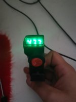
I connected the to multi meter and that showed me the voltage moved from mV to volts but the multi meter updates too slow to register the fast changes.
It won't be fast changes if you are manually spinning the wheel slowly to see how it changes...because you just spin it slower so you can see them.
")
If you're trying to see pulses while the *motor* is spinning the wheel...that could be difficult.
I have also removed the PAS 1 that I had connected to OEM PAS sensor as I could not get it working by pedaling. The OEM one had an uncomfortable latency which I associate now with all PAS sensors.
The sensor isn't the only issue with the latency--it is the design of the software that reads that and how it chooses to respond. Most of the systems are not adjustable by the user, and are very basic, not designed for performance or responsiveness, but rather for cost-reduction and simplicity (which means less options and less stuff to futz with for support personnel).
But if it is a low-pole count sensor then it takes longer for the pedals to turn far enough for it to detect a change in speed. The more poles the sensor has, the faster it's response time can be, up to whatever thepole-count-limit is of the controller reading it.
Justin_LE has some posts here and/or on the ebikes.ca site about PAS cadence sensors and how they work, that may help you see the issues.
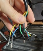
As for getting an existing PAS sensor working...remember that there are several types of them, that provide different kinds of signals, some of which use one signal pin, some use two. They also run on different voltage levels (most on 5v, though ebikes.ca has some modified ones for 10-12v so they'll run off the Cycle Analyst power, etc.)
If your sensor is a 5v unit and it's powered from 12v, it could be damaged by it. Depends on the specific hall sensor(s) used inside and any other logic circuits it may have. (some motor-type halls can go up to 30vdc, for instance, and these are the same types that can be used for cadence-type PAS sensors...but others only go up to 3v or 4v or 5v, etc--you can't know without having the part number marked on the actual internal hall sensor and finding it's manufacturer datasheet, so it is safer to assume it will run only on 5v if you don't know for sure otherwise).
Then there are the many kinds of torque sensors (which usually output a variable voltage), some of which include a cadence sensor (that still outputs pulses).
Some torque sensor units don't output a variable voltage or have separate cadence pulses, but instead use a serial bus like CANbus or 1-wire or one of the many others, and send all data to the controller that way. Those are typically only useful on the OEM controller they come with, without reverse engineering the data stream and making an MCU conversion system for it.
Your posts made a huge difference to me and I really appreciate the effort you put into this and Endless sphere in general!
Thanks--most of the ebike stuff i post about are things I learned here in the first place.
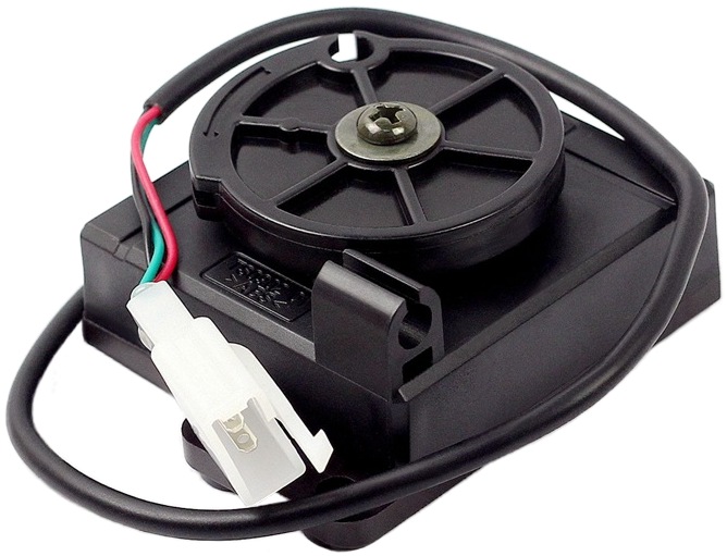
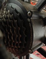
100% not clutchless. I grounded the FWD/REV pin and with the chain off, pressed throttle. The wheel spins in reverse but when I applied pressure to stop it moving I was able to stop it. Not the same torque as forward so its a clutched geared hub motor like the rest of them.
Yeah, if you can stop it by hand and the motor keeps running, it's a clutched motor that freewheels the hub casing relative to the motor gearing/etc.
So it can't do regen braking, nor can it run in reverse to back up a bike or trike/etc.
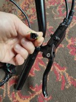
I was entertaining the idea of making an ebrake lever like the dual lever on mole grips. The smaller lever nested under the bigger was to be a second 'throttle like' regen brake. Now that I have crossed the possibility of my hub motor being clutchless ....
<snip> Knowing its a non-regen motor, the throttle with variable voltage braking is probably an overkill in non-regen bikes? Is it not a case of on/off ebrake for all but regen capable setups?
Since the motor can't do regen, there's no reason at present to add any form of motor braking control. You can use the on/off switch in your existing levers if you like, to provide a motor-turn-off signal if you like, but as long as you stop pedalling when you brake (for PAS/torque control) or let off the throttle, you don't need that either.
Trailer on regen braking makes sense to me even though I don't know how much of a problem is the added freewheel spin resistance.
Not sure what you mean. You won't have any freewheel for a regen capable motor. (not between the motor and the ground, anyway).
For an non-freewheeling motor, if you use a controller like the *runners with Virtual Freewheeling, it can be tuned to reduce the extra resistance to zero with minimal current.
How much power that uses vs what's recovered depends on how much braking you do with it vs how much distance you travel--if you go a long long way without using it's braking, it might not be worth having the function unless what you need the system to do for you simply won't work without having that braking at some point in the trip (which usually points to inadequate mechanical brakes or poor tire choice for conditions, etc).
If the reason for having regen braking is energy recovery, well, that's not typically worth it as you *might* get 5% back, or less. Probably costs less and weighs less and takes less space and is certainly a lot less complicated to just carry 5% more battery.
I know that on the clutched hub its really annoying as it stops nearly instantly when freewheeling(can't imagine what a clutchless would be like).
I don't know what you mean?
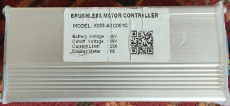
I will set the over- discharge voltage to the 13s and will rely on JBD bms fi=or the 14S.
I recommend changing the JBD BMS per-cell LVC upward to match what the controller's LVC should be for that--typically that's 3.0-3.3v. Just divide the LVC you see on a typical 52v controller by 14s (or 48v controller by 13s) to get the value you should set the BMS LVC to.
That will protect the 14s pack better, by not running it down to the minimum (which is hard on it and more likely to unbalance it). It shouldn't make much difference to your range, but the pack will last longer / run more reliably this way.