Hillzofvalp's 29er Thread... now with custom 63T (cromotor)

Figured out how to copy image links on iPad!!

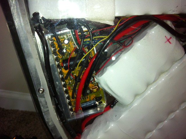
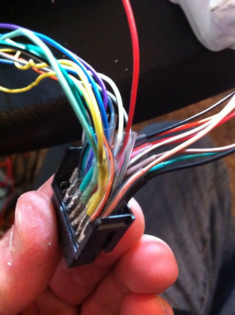
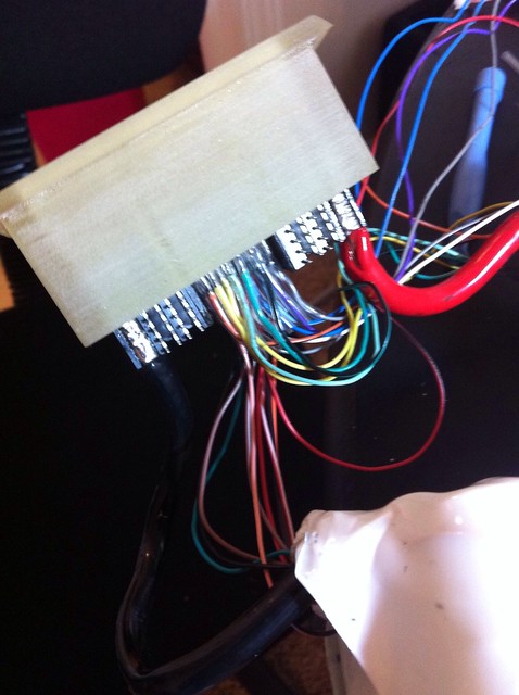
While I had the controller apart, I went ahead and put in some 12awg deans for the phases and some 8 gauge that matches the battery pack. May cut down on some heat.

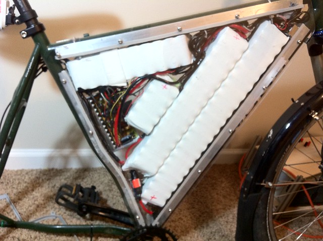
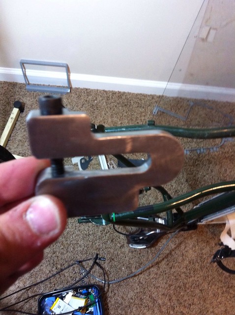
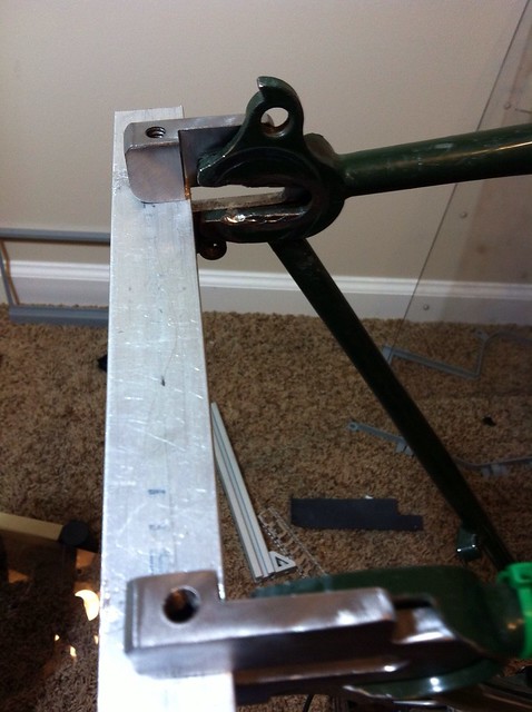
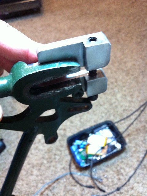
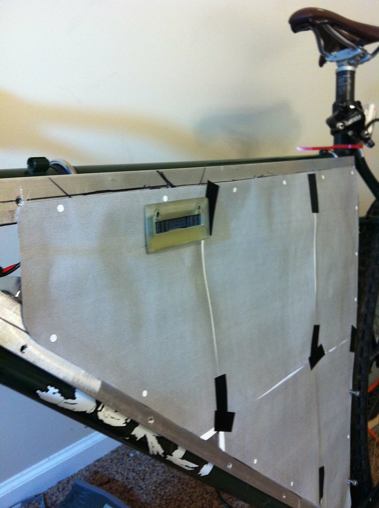
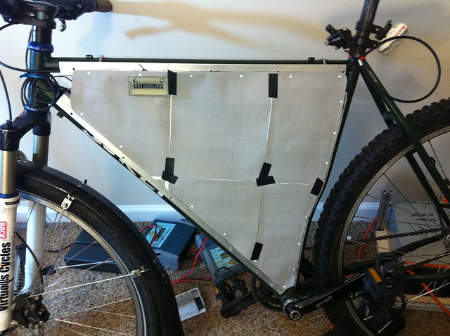
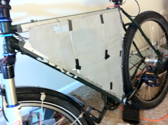
I haven't made a lid for the the controller yet, but I was just going to pound some .05 inch aluminum on it (with the board out of course) to get the conformity I want. I really just want an indentation in one area where I removed the battery pack cap. This will let me fit in everything in my triangle enclosure.

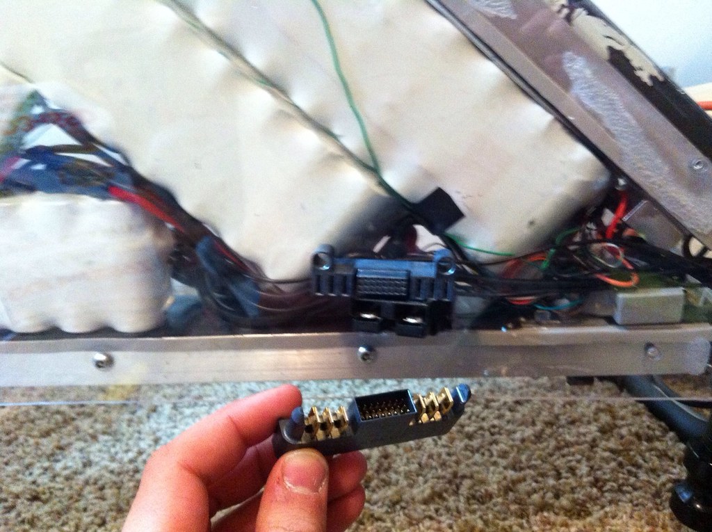
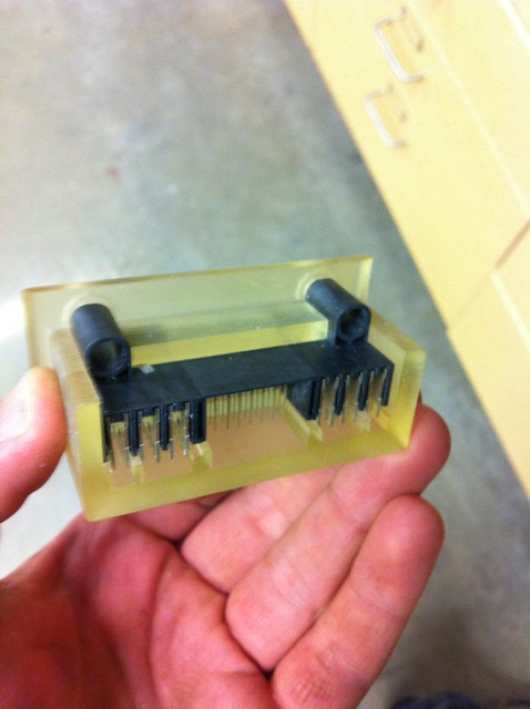
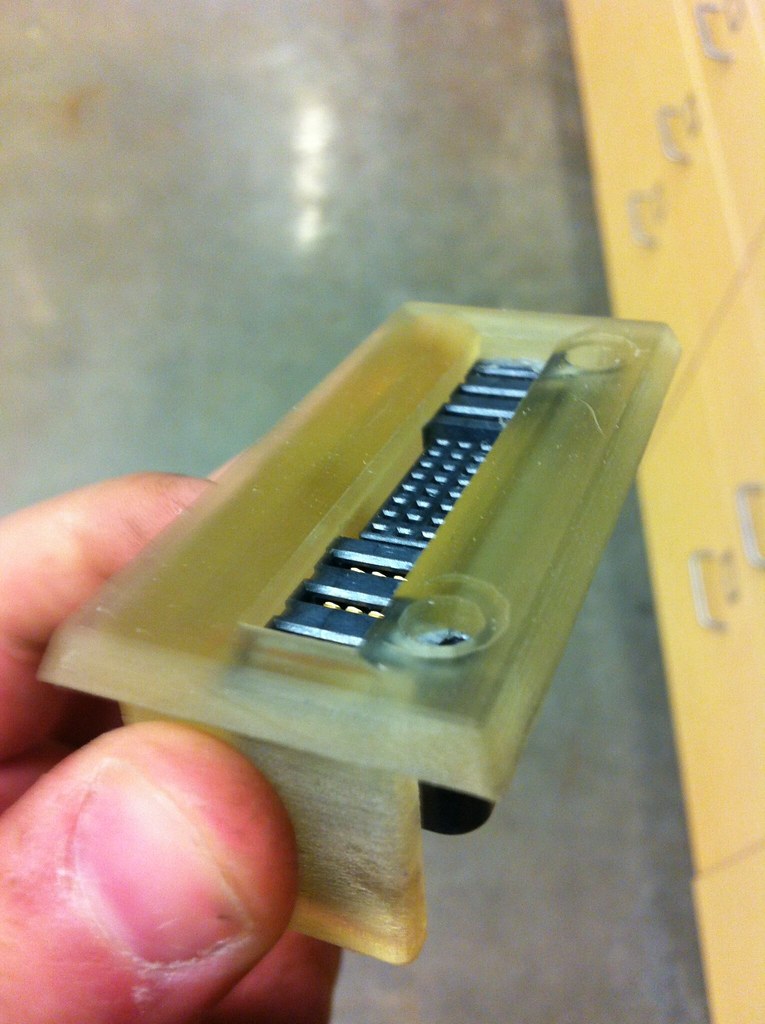
I ordered some sample connectors from molex... Ones that include both 24 signal pins and 4-6 blades for charge leads. The idea originally was to have 4 main leads: 2 for breaking into the middle of pack for Hyperion sync charging, and 2 for full potential normal leads. But then I thought, why not make the charge port also serve as an emergency disconnect.. So the cap for the receptacle will actually be another connector that shorts the mid-pack connection. This is why I tried to get a connector with 6 blades: 2 for main charging, and 4 for mid pack low resistance connection.
http://www.molex.com/pdm_docs/sd/464373007_sd.pdf

I want a cromotor, but I will have to wait until march or April when they are more affordable.
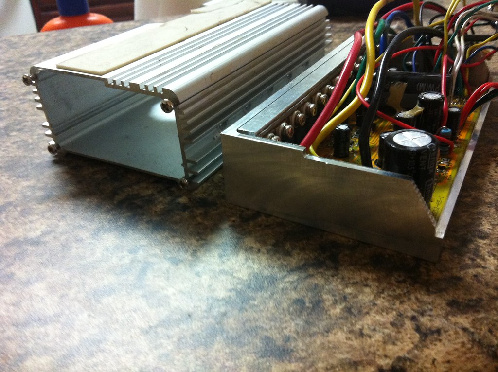
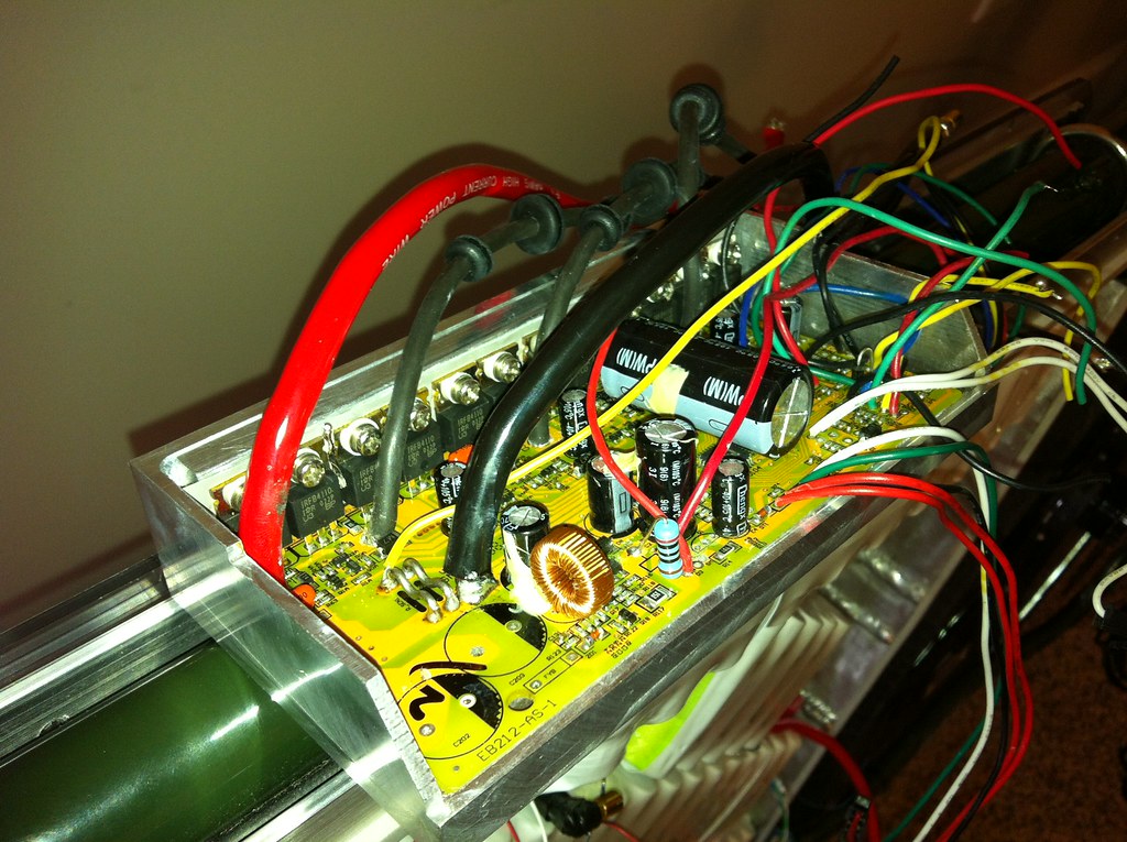
6747201243_e44218c68b_b.jpg


6747200223_329e7fd4f7_b.jpg


6747199259_800b4d6a2d_b.jpg
 
I'll have to say that 20S is a lot more fun--- up until the axle spins in the dropouts! I'm fashioning a torque arm and want to get some input (if anyone actually posts in my thread anymore). I am hoping to water jet some 1/8" stainless I have around.. Let me know if you have suggestions. I was going to bolt it threw the rack eyelet, one disc slot, and in one of the pictured gaps


6762611741_18733aff0d_z.jpg

6762612183_dd209c7d08_z.jpg


I don't know how common this type of spin out is, but notice how it left the slot and jacked out the dropout! (nut is flush with axle end). Phases left unscathed amazingly. I was on slight hill stopped at an intersection. It happened from dead stop with my pedaling hard. The uneven torque on the axle from pedaling hard one one side probably caused it.. And I shouldn't have had grease on the nord locks. Wd-40 only I'm now told. Oops

6762612515_eb767e87bc_z.jpg
 
:wink: I don't need 5 ES bucks. However, if you get me another 10S Lipo....

With 20S and full acceleration you are in need of two heavy torque arms. So you noticed... :twisted:

And with a voltage of 84-72V, I would recommend a kill switch and a maybe a fuse as well.
 
Dude, it's steel. Just weld some extra thickness to the dropouts. Make it thick enough to run 5/16th good grade bolts for clamping and be done with it. Do you have an angle grinder? Welding the thick stuff is easy, so practice a bit on some scraps and then do it. You're into DIY ebikes. You're on a good track with a steel frame already. You're spending the bucks on all kinds of other stuff including $700-800 just for a motor. What's another $200 for some more metal working equipment and supplies.

John
 
Well said John.
I would add that 1/8 thick SS torque arm will not help much to hold a powerfull hub motor.
On my first build, the X5 spinned through 3/16 SS both sides after only 500 km.

Make them dropouts overkill.
 
My first hubbie spun out too thin SS torque arms in the first 10ft of the first ride. The SS gave very little, but cut grooves in the axle like it was butter.

Think of the width of any decent wrench. Now visualize the bolt or nut heads that are only 10mm across, and then consider the entire force of motion for your bike being transferred through those little nuts as turning torque. Regular nuts and bolt heads are going to deform in no time, as will the wrenches, because it's literally thousands of pounds of force acting at that tiny radius. At a minimum you'd want double length nuts and custom wrenches with a width to match.

Just like phase wire thickness, you'd have to get pretty crazy to be overkill. On Hubmonster my 20mm wide clamping dropouts look kinda puny, and definitely aren't close to overkill, but I believe they'll get the job done.
Hubmonster clamping dropout.JPG
 
John in CR said:
...On Hubmonster my 20mm wide clamping dropouts look kinda puny, and definitely aren't close to overkill, but I believe they'll get the job done.
To someone who thinks that he can get away with a 1/8 SS torque arm, your dropouts might look way overkill. :wink:
 
MadRhino said:
John in CR said:
...On Hubmonster my 20mm wide clamping dropouts look kinda puny, and definitely aren't close to overkill, but I believe they'll get the job done.
To someone who thinks that he can get away with a 1/8 SS torque arm, your dropouts might look way overkill. :wink:

1/8 SS is exactly what cut through my axle like butter in less than 10ft of my first hubmotor ride. Of course my weight and the 25% grade didn't help matters. Thank goodness I had them well strapped on, because it was a front motor and the alloy dropouts snapped off like toothpicks, so had they not held the motor on, my hubmotor career may have started and ended with a faceplant in the asphalt. :mrgreen:
 
in an effort to make charging and balancing a much more seamless process, I have received free samples of these 60A molex connectors. They have 24 signal pins I will use for balancing.. If I ever went up to 28s I could easily add another 24 signal block(or less if they have it). Samples we free.shipping was free. CAD model access allows me to easily 3d print a grommet/mount that will nearly seal the bike.

So the plan said now is to run 4 connectors to mid pack.. 2 on each side... Cause Hyperion chargers don't like to sync charge with pack connected at midpoint. The reason for using 2 is to minimize resistance and maximize current capability for say a cromotor or dual motor setup. The the controller will be bullet connected to the pack...And the outside pins of the connector wil be for positive net and negative net charge leads (bulk charge leads).

I got an extra male to use as a cap and emergency disconnect.it will connect the 4 pins together and seal the port when ready to ride. Still haven't figured out precharge method. Both halves of the pack will each receive a 100A fuse in the event of a connector failure. Is will try to upload an image of the mount that I'm constraining in Catia.. I thought of doing it out of Al but decided that wouldn't make any sense from a time standpoint, cost standpoint, or electrical safety standpoint. So glad my school has 3 3d printers....:).. And I can do projects on them through the EV club ( no personal projects allowed)


I also may note for Hyperion users: it appears the power leads connect BEFORE the balance leads. Disconnect should be safe also. Makes sense cause these were designed for server supplies generally

Edit: It may actually be worthwhile to Put a few cell logs on the bike and integrate them into the cap
6773607343_ba5491745e_b.jpg
 
Regarding torque arms. I'm still stuck between clamping the axle vs. thick torque arms. I don't really have space for thick torque plates from doc, cause I cut the axle on my crap 9c. However for cromotor I will most likely use a modified version of docs part
 
When is someone going to come out with a cheap but reliable single cell charger? That's the route to seamless charging and balancing of Lipo, but no one uses it. Integrate Methods LVC/HVC protection board somehow for safe quick bulk charging and we'd be good to go. Hopefully these kind of solutions come by the time we can readily get NMC's. They need balancing don't they?
 
Yeah.. It's only a matter of time. This becomes a practical solution for lifepo4. In reality I don't need to balance every charge, but it's nice to log what's going on.. Cell by cell. This is more focused On having emergency cut off without a power consuming contactor. It just s happens I need to split the middle of the pack anyways.

With this type of connector you could more easily parallel a big bank of lipo for charging.. Only would require some diodes and a single 14s Hyperion for a full 28s Pack. Not ideal.

I would really like a smaller bms then the current ones. That's where ebikes are headed
 
The added benefit I didn't really realize fully is that I can. Now easily bulk charge with a lower voltage psu. 36V instead of 72. Same C rate but much more utilizing my 55A supplies.. Just make a special connector that links the right things.. Don't have to disconnect wires and open up 15 security hex screws
 
The reason I made the torque plates .5" is that I need .5" to actually thread a pinch bolt through. I will mill off 1/4" so that the net width is .5" instead of .75".

Also below is the port that I 3D printed. I am very please with the results. Molex has drawings for all their parts online, so it was very easy to use it as a reference. Fits perfectly.

6768420835_0649f9104d_z.jpg

6819447965_40e5cee9be_z.jpg

6809407369_498cbe3a64_z.jpg

6809405035_03f31e5485_z.jpg

6809407449_e08056e89e_b.jpg


Since it would be a pain in the ass to make a new top for this controller -- and since my enclosure is going to be completely sealed (already is everywhere except two spots at very top), I don't think I will go through the hassle. It looks cool this way too. It's heatsinked to the frame with thermal compound.

6823906097_67267ca1bb_z.jpg


In this picture, the polycarbonate is on. In a future revision, I hope to reduce the side panels an the aluminum edges. Before I weld them together I will mill them down to about 1/4" high. Now, at least, I have a good reference template. When I first started, it was very hard to get the geometry/shape of the enclosure right without having a prototype.

Velcro strap holds the top most pack. The bottom long pack sits on 1/16" rubber.. snugly. All other packs are velcroed to each other.

I love how it looks! 20S5P A123
6823908597_b9abe84781_z.jpg
 
Anything gonna get hot and penetrate the wrapping at a flashpoint on that lipo?
 
It's actually A123 LiFePO4. critical areas are bumpered with rubber. Most of them are double and in some cases even triple wrapped with shrink.

Because it is well-tabbed, I don't think I'll have issues with a hot point on the pack, especially at 55A peak. I do need to test some of the tabs to see when they begin to saturate

I intend on adding another fuse for the second half of the pack... mainly because of my charging methods.. though I suppose it will also protect against this sort of failure, if the hot spot is very localized, anyways
 
been waiting in line for tesla motors for almost an hour at this job fair... Appropriate time to update my build thread.

Torque plates are complete (hopefully). See pics for how they will be welded on.

The molex balance wires were a bitch to connect... But should work great. I can now use network mode on the Hyperion chargers

6842764643_be58d159cb_z.jpg

6842765269_48bfff3f35_z.jpg

6842765949_6940c9e723_z.jpg

6842766791_eed9b9e9ba_z.jpg

6842767423_fedfe07892_z.jpg
 
Nice clamping torque arms. Those will allow you to twist that throttle and hit regen with confidence for the life of your motor.
 
Thank you, sir. I hope it works out ok. I'm not even sure what type of steel it is.. and I can cold set it by over tightening the bolt. We'll see how stiff things get when it's welded on... but I think nord-locks plus dual pinches will do the trick for 10kw cromotor
 
I've been having to ride this thing with a fixed gear drive to work in order to get the dropouts cleaned up for the dp420 treatment. Rides pretty nice with no electricity! Gotta love that peace of mind of a simple bike

So I decided I really couldn't stand the current panels, especially after I got "removable" silicone sealant stuck on to the panels (I later found very soft, adhesive backed seals much more useful). Originally, I had to cut each panel out of separate 24x24x.118" polycarbonate sheets on a gantry mill. This time, I will just barely fit both panels on one sheet, saving me $25. Once I have them milled out, I will trace the edges on the aluminum, disassemble everything, and cut off all excess aluminum. This will reveal a good portion of the frame, including the surly Logo on the down tube. I hope that it will cut about 5 lbs of nonsense off as well.

Like my molex charge port? It's gonna be a pain in the ass to actually hook up (already got most of it done, but cramming it in SAFELY is my concern). When I have the new panels made, I will insert the molex holder and get an idea of the shape of the internal bosses used for securing the port. I will DP420 them (why not, I''ll have excess from TA extensions). The the whole assembly will bolt on with 1/4" bolts of some type. I'm thinking of working out a magnetic cover/seal for the port (but remember, there will be a plug inserted to enable the bike through middle 4 terminals)

I am going to get one of those long toggle switches and poke it out the top of the enclosure for my precharge circuit (so I don't have to open up the bike to disconnect precharge if I'm going to be away for a while)

THere is an extra pin on the balance connector that I may use for charging the auxiliary 4s1p 18650 battery located in the seat post (wires come out the water bottle boss). Would it be okay to ground the auxiliary pack with main pack? I don't see any real safety hazards.

6879236189_2086a453ca_b.jpg


6879236183_f47ac9097f_z.jpg


here is a comparison shot with the huge originals. It's much easier to CNC these panels when you have a functional prototype. reusing 3 of the original holes in the new panels will make alignment and hole tapping a breeze
6879235181_151cf6d307_z.jpg
 
crossing my fingers! I was kinda in a rush.. but i THINK i mixed it thoroughly. second one will get extreme care during mixing process.

I used a vice grip to pinch on the dropout to bring it back to correct size. I then used another vice grip to slowly tighten the pinch to achieve the intended dimension

Everything was cleaned with air tools, then I went in with dremel engraving tools to get all the crevices, the surly stamped logo, and to texturize things a bit. Then I cleaned everything very deeply with rubbing alcohol

6883682651_e5ff32c3fb_z.jpg

6883682177_d5f10e171f_z.jpg

6883681501_fabaf532df_b.jpg

6883680105_845b0aac80_z.jpg
 
Back
Top