• Hello ES! We could use some help to get us past the finish line on building the new knowledgebase for the forum.
    Can you donate? Please see our fundraising page. Thank you!

Hypothetical bike build. (Electrifying a Surly Moonlander 2.0 with Pinion Gearbox for max range)

Controllers do not have unlimited ability to step up battery current. Most will double it and some will triple it in the right conditions. Do you think a 48V 25A rated controller will deliver as much maximum current as a 24V 50A controller? If so, explain.
I think a 48V 50A controller will apply the same amount of current as a 24V 50A controller. You should use a controller is that is capable of more current than you will need and set it's limit to what you want not use use a controller that is less capable than what you want?
Also every controller has a most efficient range above 3/4 of its free speed. How can a 48V controller running at 3/8 of its free speed compete efficiency wise with a 24V controller running at 3/4 of its free speed on the same slope?
You are confusing things you've heard, motors are often most efficient at around 3/4 of free speed not controllers. And that is just a general rule of thumb that assumes you are running a motor at roughly it's intended operating range including load.

Yes, the other person said power and not speed, but it's not useful to attack every idea like this compared to strong manning arguments to enable a more productive conversation.
I don't where I steel manned anything here, if anything I gave numerous caveats where the idea could work in some areas and even suggested things similar to it that do work. I don't think my language was too aggressive or an "attack" I was trying to be as factual and explain things the best I could.

Regardless I'm done filling running this thread off the rails, if you want to discuss the idea further start a new thread.
 
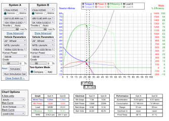
I believe what I modeled in the Grin simulator in post #74 matches what was described, using consistent assumptions/components in both systems for things not specified. Let me know if there are any errors or inconsistent assumptions. The exercise is really about maximizing performance with the batteries you’ve got, which are two fairly weak low voltage batteries. Even though they are weak, they can still manage 30mph, but dog crap slow getting there, but it gets there. But it’s totally gutless for getting up a steep parking garage ramp in high speed mode. So, at the ramp, you switch to double torque mode, ride up at 10mph, then switch to 150% speed mode for the street.

PS. The simulator does not model battery current capability directly. That is done by setting the custom controller battery current limit for purposes of running the simulation.
 
Last edited:
The factory rim and tire will be just fine unless the tire pressure is super low maybe but at some point spinning tires on rims seems pretty rare. I've only had it happen with extreme amounts of torque, very low tire pressure and very old tires where the rubber on the bead was partially rubbed through, I ended up fixing it with bead locks though as I like my low tire pressure. I think though those tires will suck up a fair amount of battery.
I admit I'm very ignorant when it comes to bicycle components. Is there such a thing as bead locks on a bicycle rim? I thought that was a drag racing kinda thing or rock crawling, that would be really cool to run low pressure tire with a bead lock and don't worry about the tire coming off the rim.

As for the part where we try to make to motor have two speeds (as far as I understood it), I feel like that is rather redundant, as I already have the pinion gearbox before the motor, so to me it looks like we are trying to solve a non-existing problem. I do admit I might have completely misunderstood that part. :)

I was thinking on a 72V battery/s, but if people think there's something to that idea of different batteries I don't mind the discussion. What started as just a discussion might actually turn into a build thread. :)

The trouble now is that those couple of weeks that I have to wait for the shipping of the bike won't go by at all... :)
 
I believe what I modeled in the Grin simulator in post #74 matches what the OP has described, using consistent assumptions/components in both systems for things not specified. Let me know if there are any errors or inconsistent assumptions. The exercise is really about maximizing performance with the batteries you’ve got, which are two fairly weak low voltage batteries. Even though they are weak, they can still manage 30mph, but dog crap slow getting there, but it gets there. But it’s totally gutless for getting up a steep parking garage ramp in high speed mode. So, at the ramp, you switch to double torque mode, ride up at 10mph, then switch to 150% speed mode for the street.

PS. The simulator does not model battery current capability directly. That is done by setting the custom controller battery current limit for purposes of running the simulation.
He doesn't talk about batteries being a limiting factor at all, only about the motor and controller efficiency and power.

I think what you overlooked in your simulation and what Apart insists on is the motor current. Here is an example and I'll try to explain everything I did carefully.
1779370984471.png
OK so first, everything the same, same motor, both all fully throttle. Now the battery of course same as if you had two packs and series paralleled them. These are wimpy batteries as you said, they are the limiting factor so they can only output 5A in series or 10A in parallel.

Controller can output 100 phase amps (called mtr amps in the sim) because we want as much torque as we can get. In your sim you changed the motor amps to half by using a controller with half the motor amps for the higher voltage battery setup as Apart suggested. But why? You can just use a controller limited to as many motor amps as the motor will take.

So you can see the curves line up the whole way through acceleration, same efficiency, same torque, same power from the battery, higher voltage battery setup draws half the current but twice the voltage so same power. So the battery is the limit the whole way through.

I know it seems like a free lunch but it's just you aren't changing the motor so the same motor will act the same with the same current. There are losses involved in increasing the speed with more battery voltage, primarily magnetic ones but this tend to balance out well in our uses because we are using motors that are well sized to the application.

I admit I'm very ignorant when it comes to bicycle components. Is there such a thing as bead locks on a bicycle rim? I thought that was a drag racing kinda thing or rock crawling, that would be really cool to run low pressure tire with a bead lock and don't worry about the tire coming off the rim.
That's because they aren't, I've seen one guy make one for fatbikes using a pretty complicated internal tube spreader thing. The ones I have I made, designed after dirbike ones which just use a wedge inside that pinches the bead against the rim using a bolt through the rim, very simple, very effective at preventing spinning the tire but not at holding air in a tubeless setup like that other guy's one. That bike has tannus inserts and TPU tubes (it's not a fatbike).

I'm working now on better fatbike tire setups, I have some ideas on how to balance super low pressure, damping and pinch flat protection. I think it's possible and I think the improved damping will really make a fatbike ride super nice and have stupid traction.
 
That's because they aren't, I've seen one guy make one for fatbikes using a pretty complicated internal tube spreader thing. The ones I have I made, designed after dirbike ones which just use a wedge inside that pinches the bead against the rim using a bolt through the rim, very simple, very effective at preventing spinning the tire but not at holding air in a tubeless setup like that other guy's one. That bike has tannus inserts and TPU tubes (it's not a fatbike).

I'm working now on better fatbike tire setups, I have some ideas on how to balance super low pressure, damping and pinch flat protection. I think it's possible and I think the improved damping will really make a fatbike ride super nice and have stupid traction.
Very interesting! I was thinking of going to 19inch mx rims custom drilled so they can be laced with the Max45, but that adds way to much weight on the outer most rotating part of the wheel and I don't know how that will go, tho a set of dual sport mx tires will outlast the bike lifspan... :D
 
Controller can output 100 phase amps (called mtr amps in the sim) because we want as much torque as we can get.
Wanting your controller to multiply battery amps by 10X or 20X is not the same as it doing that. I have not messed with every controller around, but the ones I have worked with can deliver 2X to 3X phase to battery current ratio.
 
He doesn't talk about batteries being a limiting factor at all, only about the motor and controller efficiency and power.

I think what you overlooked in your simulation and what Apart insists on is the motor current. Here is an example and I'll try to explain everything I did carefully.
View attachment 388529
OK so first, everything the same, same motor, both all fully throttle. Now the battery of course same as if you had two packs and series paralleled them. These are wimpy batteries as you said, they are the limiting factor so they can only output 5A in series or 10A in parallel.

Controller can output 100 phase amps (called mtr amps in the sim) because we want as much torque as we can get. In your sim you changed the motor amps to half by using a controller with half the motor amps for the higher voltage battery setup as Apart suggested. But why? You can just use a controller limited to as many motor amps as the motor will take.

So you can see the curves line up the whole way through acceleration, same efficiency, same torque, same power from the battery, higher voltage battery setup draws half the current but twice the voltage so same power. So the battery is the limit the whole way through.

I know it seems like a free lunch but it's just you aren't changing the motor so the same motor will act the same with the same current. There are losses involved in increasing the speed with more battery voltage, primarily magnetic ones but this tend to balance out well in our uses because we are using motors that are well sized to the application.


That's because they aren't, I've seen one guy make one for fatbikes using a pretty complicated internal tube spreader thing. The ones I have I made, designed after dirbike ones which just use a wedge inside that pinches the bead against the rim using a bolt through the rim, very simple, very effective at preventing spinning the tire but not at holding air in a tubeless setup like that other guy's one. That bike has tannus inserts and TPU tubes (it's not a fatbike).

I'm working now on better fatbike tire setups, I have some ideas on how to balance super low pressure, damping and pinch flat protection. I think it's possible and I think the improved damping will really make a fatbike ride super nice and have stupid traction.
Maybe a real world example might support you idea a bit better. The simulator creates very odd results when you put in values not based in reality.
I think it’s obviuos to conclude that the batteries are providing their max current in the two configurations, for most, but perhaps not all folks.
‘If you have two batteries of the same voltage and two controllers, you could switch between half voltage and double current or double voltage and half current.”
 
Last edited:
Wanting your controller to multiply battery amps by 10X or 20X is not the same as it doing that. I have not messed with every controller around, but the ones I have worked with can deliver 2X to 3X phase to battery current ratio.
In that example that is not happening, the motor current stays quite low, there is no magic here. The motor current is the same for both battery setups the entire time.
Maybe a real world example might support you idea a bit better. The simulator creates very odd results when you put in values not based in reality.
I think it’s obviuos to conclude that the batteries are providing their max current in the two configurations, for most, but perhaps not all folks.
‘If you have two batteries of the same voltage and two controllers, you could switch between half voltage and double current or double voltage and half current.”
I mean the simulator, simulates, pretty accurately in most cases and the cases that I'm aware of where it fails we have not entered into (eg motor saturation).

Here we have the controller current set low, no magic "multiplication" of current
1779378749573.png
Lets bump that motor current up a little so it matches lower voltage battery
1779379113058.png
Still no dice, ok well what about we bump it up more, now the motor current is twice the higher current battery config so we are not limiting it there.1779378893022.png
These values all seem pretty reality based to me, I mean pick any values you want you just need to keep the phase current setting the same because saying a lower current controller has less torque is just a fact. The motor doesn't care what the battery voltage is, it cares how much current it gets and to it 100% duty cycle at 24V is the same as 50% duty cycle at 48V.

Yes there are good reasons to select the correct motor and battery but we aren't in those areas, we are using a motor that is reasonable for the application, not one that is way too small or way too large, we are spinning it at reasonable speeds for it's design, it's a hub motor after all. And we are operating at reasonable voltage and current levels for it's design. Those weird edge effect losses are very small and the motor does what the motor does.
 
In that example that is not happening, the motor current stays quite low, there is no magic here. The motor current is the same for both battery setups the entire time.

If you keep setting the simulator for the same max current on both controllers, then yes. That is not how controllers rated to deliver twice as much current work.
 
That is not how controllers rated to deliver twice as much current work.
I have no idea what you mean here, please explain how controllers work then. Are you saying just because I halve the voltage to a controller I can use one that outputs twice the current and the motor will be fine with that much current? Can I halve it again and double the current? Can I keep doing that until I can put infinite current into the motor?

Eh whatever I think I probably proved the point to anybody reading, you seem to have no interest in actually explaining how you think things work and I'm not having fun explaining this over and over so unless you have some actual facts to explain your point, rather than your gut, some things you heard, some vibes, whatever you're going on here lol.
 
I should probably change the title of this thread to something like "Electrifying a Surly Moonlander 2.0 with a pinion gearbox for max expedition range" since I already ordered the bike?
 
Maybe try to mount a CYC X1 Pro to the Pinion gearbox: https://www.cycmotor.com/x1-pro-gen-4
And a hubmotor with regen braking in the front wheel.
I suppose, I could use a normal mid-drive motor as a "jackshaft" in the space between the rear tire and the seat tube, and forgo the whole regen, but I don't really like the geared motors, be it mid-drive or hub. I much rather have the simplicity of the DD hub motor + the regen. If I go the route of two motors, I'd probably just use two dd hubs in each wheel.

I kinda like the idea of being able to switch from analog to electric-assisted. Incorporating a mid-drive to this set up would be to much of a hassle when swapping from one to the other, where if I have 2 sets of wheels (the original wheels and tires and a second pair with hub motor/s), I can just leave the cables and perhaps the controller on the bike and everything else can be taken off and swapped "easily".

P.S. That saddle on the bike of your profile picture looks really comfy. :)
 
I think, I might have figured out something that is not that difficult to execute and checks all the boxes I need, I just need to ask Quilbix to make me a frame that can accept a pinion c.1 gearbox instead of normal BB.

⚙️ Full Mechanical & Electrical Specifications

1. Frame & Cockpit Integration
  • Chassis: Qulbix Q140MD Cr-Mo Steel Frame Kit, maximizing internal capacity and using front ram-air ducts for cooling.
  • Human Transmission: Pinion C1.6 internal gearbox (6 gears, 0.950 underdrive to 0.320 overdrive)
  • System Controller: Fardriver ND72450 Sine-Wave Controller (14kW peak capable) with Bluetooth and CANBUS, safely capped via software to a strict 50A battery current draw limit (3,600 Watts peak). Phase current is set to 120A–150A for torque multiplication.
  • System Computer: Grin Cycle Analyst V3 (CA3) acting as the main processor, intercepting analog pedal inputs and outputting a translated voltage to the Fardriver throttle pin.

2. Power Plant: Leaf 2000W "2026 Black Lightning" Core
  • Stator Material: 0.35 mm ultra-thin silicon steel laminations minimizing magnetic drag.
  • Upgraded Phase Wires: Factory 4.0 mm² high-temperature silicone wires (11 AWG equivalent) handling up to 150A phase bursts up inclines without voltage drop.
  • Thermal Safety: Integrated NTC temperature thermistor mapped to the CA3. Soft thermal throttling initiates at 90°C, with a hard emergency shutdown set at 130°C to eliminate risk to the magnets.
  • Total Battery Capacity: 72V 65Ah pack (4,680 Wh total / 4,212 Wh usable at 90% Depth of Discharge) nested securely in the frame center.

3. Dual-Stage Chain Transmission Architecture
  • Stage 1 (Speed Step-up Line): A 45T Pinion output sprocket drives a freewheel single-chain sprocket on the input side of the jackshaft axle (2.81x step-up).
  • Human Torque Sensing: A BeamTS chain tension sensor clamps to the frame directly under the Stage 1 chain, outputting a clean 0–5V analog signal to the CA3 tracking real-time pedal pressure.
  • Stage 2 (Torque Multiplier & Regen Path): A fixed 16T sprocket on the output side of the jackshaft drives a fixed 42T sprocket on the rear wheel hub via a secondary independent chain (2.625:1 reduction).

[ Pinion C1.6 Gearbox ] ───(45T)───> [ Stage 1 Chain Line ] ───> [ Freewheel Sprocket ]
│ │
[ BeamTS Tension Sensor ] [ Q140MD Jackshaft Axle ]
│ │
[ Rear Wheel Hub ] <──────(Fixed 42T) <── [ Stage 2 Chain ] <────── [ Fixed 16T Output ]


📊 Gear Performance Matrix (Based on 90 RPM Human Cadence)

Gear SelectionInternal RatioRear Wheel RPMFinal Ground SpeedPractical Terrain Focus
Gear 10.950 (Underdrive)100.8 RPM12.5 km/hContinuous 30% Ski Slope Climb. 87% peak motor efficiency, safe 54 Nm motor torque, zero thermal risk.
Gear 20.764125.4 RPM15.6 km/hTechnical trail riding or steep gravel access roads.
Gear 30.615155.8 RPM19.3 km/hMild singletrack or rolling off-road hills.
Gear 40.495193.6 RPM24.0 km/hStandard low-speed urban city commuting.
Gear 50.398240.7 RPM29.9 km/hRapid paved road transit.
Gear 60.320 (Overdrive)299.4 RPM37.5 km/hFlat-Ground Cruise. 100% natural voltage balance, zero electronic field-weakening tax, maximum mileage.
You're gonna take an e-moto like that and do 15 MPH?
I would go with a regular bike and a 35-40AH 36-60v battery and 1 BBS03 motor.
Don't make your expectations unrealistic.
 
Back
Top