Idiots guide to rewinding Revolt 120 pro

You might as well do it, after all it is collecting dust on the shelf now? At best a rewind will render you with a working motor. Maybe do hall upgrades as well. At worst, put motor back on shelf.
 
@wheazel: It's certainly worthwile to start, stator prep and stripping takes some time. For wire choice and turn count it might be good to see how it goes for me..

I think the motor might be OK after only a little love and new halls though. Crazy thing is that for flattish road driving i don't need more motor than i have currently, since it takes 5 seconds throttle to top speed it doesn't get warm. If it's instead geared for 80-100 km/h or going offroad that would change.. :|
 
larsb said:
@wheazel: It's certainly worthwile to start, stator prep and stripping takes some time. For wire choice and turn count it might be good to see how it goes for me..

I think the motor might be OK after only a little love and new halls though. Crazy thing is that for flattish road driving i don't need more motor than i have currently, since it takes 5 seconds throttle to top speed it doesn't get warm. If it's instead geared for 80-100 km/h or going offroad that would change.. :|

No shorts! That's a relief indeed! Makes me more confident to start. Yes I do get that the motor might be okay as is with some hall signal improvement.
However my motor is working as it is now, I just don't like the efficiency, and that is surely partly because the hall signals, but bad copperfill does not help.

Oh the decisions, its not like I have no other projects to handle with a wedding in 5weeks, a lot @work, the winter quad and experimental 3dprinting projects.
Adding to this, I don't have a direct use for the motor :D, would probably be a custom aluminum frame for off road fun.
That's less work than the winter quad for example, but still plenty, and many hours to complete.

What do you think is the best course of action with the halls Lars?
 
I am leaning towards external halls on the mounting bracket, no issues with interference there, easy replacement and possible adjustment if need be. I will do both that and internal halls and try.

There's still a lot of stuff to be done:
2 coils
Solder coils and phase wires
Glue and wire internal halls
Replace bearings
Paint rotor black - poor surface treatment and corroded magnets today..
Pot stator with heat transfer compound
Assemble
Wire external halls
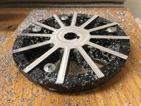
Mill magnet holes in end cover
Face mill end cover on non drive side - i want less width
Mill new mounting bracket - i will gain 5-10mm clearance on drive side for better chain management

I am also considering milling belt drive sprockets on the longer term :D
 
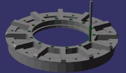
I have started on the CNC program for the hall magnets milling, close to finished with it now :D
magnets milling.jpg
It's totally possible to just glue the magnets on the existing surface but i wanted a bit more clearance to the planned (larger) 8awg phase wires.
Magnets will be countersunk to 1.5mm depth.
 
Good stuff in this thread! Sub! :mrgreen:
 
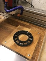
I milled a 120mm circle in a fixture plate, you can barely see it on the pics. Then clamped the 120mm diameter cover in this recess and got a perfect location - Then i milled the holes using the same center as the fixture.
Easy-peasy-lemon-squeezy! 8)

I had to stop before the first hole and manually rotate the cover until the mill hovered over my marked location on the cover. On my motor one of the screw holes align perfectly between two magnets so finding the starting spot was easy.
 
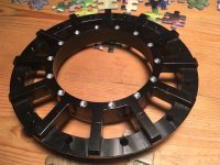
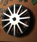
Milled the other cover tonight, turned out really well. It now looks like one of the chinese hotrodded scooter hubbies :D
image.jpeg
image.jpeg
I will have to paint it black together with the magnets.

With the flanges gone i'll not get the same airflow but i have planned for active fans. Coming later on :D
I might be in for a surprise with the possibility of screaming fan noise..
 
I'll do the last coil this weekend. It will be a lot tighter since it is flanked on both sides with other coils. I am also considering to skip the internal halls completely to save some work - on the other hand i'll miss out on the chance to know the difference between the internal and external ones.. I'll see what i have the energy to do. :wink:

I am thinking about how to join the coils together since space is limited, soldering and shrink sleeving will be tough to do properly and fit with the larger phase wires.
TIPS or pointers appreciated!
 
Really exciting to follow now as the final sprint approaches. Keep up the momentum.
 
Thanks macribs. I got to finish this soon or i'll lose the oomph and take summer. 8) luckily it's been raining today!

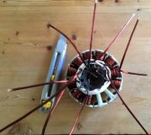
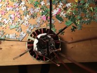
12 down, finished winding!
image.jpeg
I'll wrap one extra turn on all coils with the excess wire and connect them, then i'm on the home straight!
 
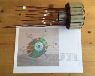
I marked all the starts to avoid confusion and removed the tape. Do you see the error?

Should've been more thorough on the starting lengths.. There are also two ends that stick out, one less turn on these as compared to the others.
image.jpeg

I'll have to thread through the final turns to get them in the place i want. Will put some heat shrink on the wire ends to protect from scratching other wires in the process.
 
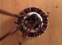
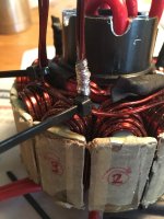
Hooked up phases tonight. The 8awg really is on the limit for size, it doesn't fit - yet. I'll string it down or use a spacer for the bearing to secure clearance.


The stiff coil wires are tough to get in the right place, i let them go out to the side together with the 8awg, wrapped it with some bare copper wire and used double tie wraps to keep the bundles together before soldering. Quite good result apart from that they are too large :D

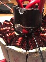
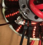
A drop of solder fell into the coils, means i might have created a short on two coils. Damn! Cannot really measure it now that the coils are joined either. Double damn!
image.jpeg
image.jpeg
image.jpeg

I'll just hope for the best or a fun fire first time i use it 8) 8)
 
I don't know about the insulation on that particular copper wire, but my general experience with coated wire for electric motors is that the coating is very tough.
It is close to impossible to melt the coating with solder and some grinding with a sandpaper is needed to clear the coat. is it visible that the solder drop affected the wires?

Good luck with the tests! Looking so good.
 
i think you are correct, the insulation is really tough so should probably be fine. The solder drop was large and lodged itself in between two coils, i have no way of knowing how bad it is.
I have more wire but no more endurance to rewind if the motor does not run!
 
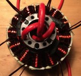
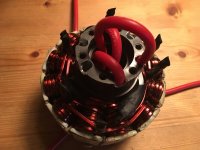
All coils connected. All the toughest work is done. I am really looking forward to closing the motor again - it is not far off! :D :D
image.jpeg
image.jpeg

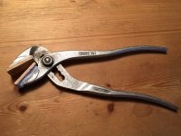
I hacked some pliers with wood jaws to be able to squash down the phase wire ends after melting the solder. Now ends can fit below the bearing surface (but it's still very tight)
image.jpeg
 
Back
Top