KT motor controllers -- Flexible OpenSource firmware for BMSBattery S/Kunteng KT motor controllers (0.25kW up to 5kW)

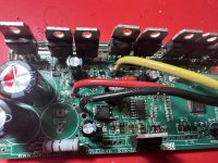
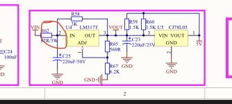
DC/DC stepdown from the 36V display supply (like the wiring diagrams in this thread). I suppose it could be that it is somehow getting bad power or interference when motor is under load. I'll try a seperate source and see if that makes an impact.
 
Just few weeks ago i got broken the axle of SEMPU 4. The axle broke exactly at the edge of double bearing. I know i should not use it for (even small) MTB drop jumps :(
IMG20220719205853 m.jpg
IMG20220719205900 m.jpg
IMG20220719210118 m.jpg
IMG20220719204008 m.jpg
IMG20220719205656 m.jpg
IMG20220719210810 m.jpg
IMG20220719210815 m.jpg
IMG20220719210318 m.jpg
IMG20220719210321 m.jpg
IMG20220719210325 m.jpg


Already got the replacement sensor and got a chance to measure the sensitivity at very low pressure which makes me sure this one is better for lighweigth riders :)
[youtube]https://youtu.be/007nm_REen8[/youtube]
 
How to use the S06P for motor current control with a throttle?

--- If this question has already been answered on the forum, please let me know ---

Maxun-e-kit-main-board-fill-359x223.jpg

Bluetooth-Wattmeter-4x-fill-594x165.jpg


I built an extension board for the motor controller S06P, https://www.avdweb.nl/solar-bike/el...er-extension-board-for-ebike-motor-controller.

(The S06P is used because the motor has no integrated Hall sensors and I need motor current control instead of voltage control)

Problem
I want to simply control the motor current from 0-15A by the throttle input 0-4V. But it turned out that the S06P requires a PAS sensor too. It uses torque simulation of which it is not described how it exactly works. Who know more about this?

Questions
Is it possible to use a standard S06P here fore, so without reprogramming?
If not, maybe it is possible to use a square wave signal to the PAS input, instead of 0-4V to the throttle input?
Has anyone carried out reprogramming the S06P before?
Does the S06P work from standstill 0 km/h?
 
avandalen said:
Is it possible to use a standard S06P here fore, so without reprogramming?
You just have to set the parameters to the right values with a Kunteng display once. See the manual of a cheap KT LCD3 e.g.
https://www.bizobike.com/uploads/5/7/0/9/57094291/handleiding-bizobike-kt-lcd3.pdf
(P4 =1 should do the job, but I am no expert in the original Kunteng system, ask @stuggibuggi at the german forum)

But be aware, you will never be able to control the motor current directly (means the motor torque) as the Kunteng can't measure two phase currents. You could measure the dutycyle by your external board and calculate back the motor current from
battery current = duty Cycle * motor current.
But I guess your aim is to control the battery current or the electrical input power, not the torque of the motor....

regards
stancecoke
 
Thank you for your help.

>>You just have to set the parameters to the right values with a Kunteng display once.
So, after doing this, I can disconnect the display forever, the setting is stored in EEPROM in the processor of the S06P?

>>as the Kunteng can't measure two phase currents.
The S06P measures the total motor current via the shunt, and this is proportional to the power, what do you mean with the two-phase currents?

The opensourceebikefirmware is not for the S06P (controllers for sensorless motors) ?
 
avandalen said:
So, after doing this, I can disconnect the display forever, the setting is stored in EEPROM in the processor of the S06P?
yes.

avandalen said:
The S06P measures the total motor current via the shunt, and this is equal to the torque
No, the DC rail shunt only measures the DC battery current. The motor current that is responsible for the motor torque has nothing to do with the DC current from the battery.
https://support.maxongroup.com/hc/en-us/articles/360016161594-Motor-controllers-Input-current-versus-Motor-current-Power-Conversion

avandalen said:
The opensourceebikefirmware is not for the S06P (controllers for sensorless motors) ?

no, it's only for sensored motors.

regards
stancecoke
 
>> No, the DC rail shunt only measures the DC battery current. The motor current that is responsible for the motor torque has nothing to do with the DC current from the battery.
Yes you are right, but I'm interested in just the motor power because I want to control in steps 50W, 100W 150W etc.
 
Wanted: Open source firmware for S06P
The S06P is for motors without integrated Hall sensors. I can't use the S06S.
I need this for the Maxun e-kit https://www.avdweb.nl/solar-bike/electronics/bluetooth-wattmeter-extension-board-for-ebike-motor-controller
Who is also interested in firmware for the S06P?
 
I am having a strange problem with my assist level automatically being set to zero mid ride, and I can't quite figure out why. To get the motor working again, I simply use the display to set assist back up to the desired level. Note, the display never turns off or loses power, it remains on the entire time.

I'm using Torque From X4 firmware and a KT-LCD5 controller.

I have looked through the source code and cannot seem to find any location where assist level is being set to zero. Only place I can see ui8_assistlevel_global being set at all is either in display.c when data is received from the display, or in the controllerstate_init function.

I thought perhaps under voltage detection or something like that might revert assist to zero, but it does not.

The controller is definitely not overheating, it and the motor is barely warm when it happens.

My next test will be to run the controller without the display just to rule out anything being caused by the display itself, but if anyone else has experienced anything similar I'd love to hear about it.
 
Major Clod said:
My next test will be to run the controller without the display just to rule out anything being caused by the display itself, but if anyone else has experienced anything similar I'd love to hear about it.

For anyone who might read this, bike runs perfectly fine when setup with no display. So the issue is either my display itself, or possibly related to the code that talks to the display. I may try to find a cheap alternative to rule out a faulty display, but as this is a kid's MTB I want it to be relatively set and forget anyway
 
Can you try this LCD on stock firmware ? Or connect with other display? I have not tried LCD 5 but had comm issue (no communication) when battery monitoring on LCD 4 was set to real time P5 set to "0". But your case may have different root cause.
 
Does anybody have a stock firmware for KT24/36ZWS aka S06P sensorless controller? Or has someone ever uploaded it to the forum?
Thank you in advance!
 
Hi! I've been thinking about flashing my KT36/48SVPR with this firmware. I have read all the docs on both the website and GitHub page of this project. But I still have some of my questions unanswered.

1. The Github page states that the P and C parameters on the LCD3 have been mapped differently, but there is no instruction or mapping that explains what C and P states have been moved. Another part of the wiki states that only the speed and wheel size are adjustable on the LCD3 but does that mean that the rest of the "greyed out" settings only are configurable with the Blueosec app?

2. My controller came with a KT-BLE Bluetooth dongle. I have tried to connect it to the Blueosec app without flashing the firmware but as soon as I tried to pair it with my phone via the Bluetooth settings it rejected the connection because of a wrong pin. Have anyone tried to use the firmware with the KT-BLE or does anyone know the required pin?

Thanks in advance
 
Angrubean said:
Have anyone tried to use the firmware with the KT-BLE or does anyone know the required pin?
The original bluetooth module only works with the original firmware and the original Kunteng app:
https://pan.baidu.com/s/1HnDPgTLK1sHdQpHlKrGeDg

Code: aw8n

117-1.png


https://opensourceebikefirmware.bitbucket.io/development/Motor_controllers--BMSBattery_S_series--Kunteng_mobile_app.html

regards
stancecoke
 
stancecoke said:
Angrubean said:
Have anyone tried to use the firmware with the KT-BLE or does anyone know the required pin?
The original bluetooth module only works with the original firmware and the original Kunteng app:
https://pan.baidu.com/s/1HnDPgTLK1sHdQpHlKrGeDg

Code: aw8n

117-1.png


https://opensourceebikefirmware.bitbucket.io/development/Motor_controllers--BMSBattery_S_series--Kunteng_mobile_app.html

regards
stancecoke

But is it possible to change the speed or other parameters through the LCD? or is it only possible through a flash of a modified firmware?

Sorry for the stupid questions. I'm new to this and the wiki doesn't give a clear answer.
 
szkuba said:
Can you try this LCD on stock firmware ? Or connect with other display? I have not tried LCD 5 but had comm issue (no communication) when battery monitoring on LCD 4 was set to real time P5 set to "0". But your case may have different root cause.

I did just receive another controller from Aliexpress so I'll definately try it out. The display was working ok stock when I originally tried it, but that was some time ago.
 
Hi,
in case someone is struggling to get BluOSEC app to work (it crashes on start), here's what you can try.
The culprit is SDCC 4.2.0, which for some reason doesn't want to operate properly with current master branch. The results are the following:
  • It renders previously flashable setups corrupt (controller will drain only 20mA)
  • Flashing freshly cloned master will result in BluOSEC app crashing
  • Produces otherwise no errors anywhere (log, onscreen)
The solution for this should be fairly simple. Uninstall SDCC 4.2.0, reboot your machine, and then install SDCC 4.1.0 (2nd reboot just in case)
4.1.0 package can be found here: https://sourceforge.net/projects/sdcc/files/sdcc-win64/4.1.0/
I have also archived it in case the repo goes offline at some point.

I'm hoping to add full explanation to the wiki at some point, but recently got quite busy at work. :(
 
Hey guys,

I know it's a tiny bit off topic but you guys know your stuff regarding KT controllers.

My KT controller 5V rail had died. No throttle input no PAS, LCD working perfectly & no errors on LCD.

I have changed BOTH voltage regulators with hot air gun etc with new ones and it's still the same. FETS are all good and charging and discharging.

I'm wonder if anyone has a schematic of the 5V rail or had any more suggestions.

It's the KT 30a peak 15a rated version.

Any questions question ask :) thanks guys
 
Hey guys,

I know you guys know your stuff regarding KT controllers.

My KT controller 5V rail had died. No throttle input no PAS, LCD working perfectly & no errors on LCD.

I have changed BOTH voltage regulators with hot air gun etc with new ones and it's still the same. FETS are all good and charging and discharging.

I'm wonder if anyone has a schematic of the 5V rail or had any more suggestions.

It's the KT 30a peak 15a rated version.

Any questions question ask :) thanks guys
 
You'll find some links to a schematic on page 160 of this thread. It may not be exactly correct for your your controller but the 5/15v supplies seem to be fairly generic across these KT controllers.

If you''ve changed both the regs and have a supply to the controller it's probably worth checking the large series resistor (R62?).
 
Found R63 which is reading 263ohms.

I don't know where R62 is on the board ?

I should mention I did a small shunt mod and the issue happened after I did that.

Voltage is 58.8v (52v battery ) between +ve & -ve There's no power going into LM317t so it has to be something before that on the rail surely ?

I've attached some snaps of the schematic and a pic of the board so maybe you can direct me.
 

Attachments

  • 829E94DE-B60E-4CA7-9F2B-11780159FDB7.jpeg
    829E94DE-B60E-4CA7-9F2B-11780159FDB7.jpeg
    2.9 MB · Views: 90
  • A2F264AA-EB0B-4013-8982-D8F0BECE5531.jpeg
    A2F264AA-EB0B-4013-8982-D8F0BECE5531.jpeg
    268.4 KB · Views: 92
  • 9CE8EBA9-0840-4CCC-B57E-257F36945ECE.png
    9CE8EBA9-0840-4CCC-B57E-257F36945ECE.png
    1.2 MB · Views: 91
Update :

I am getting between +ve of controller & INPUT leg of LM317T regulator 5.1v

I am also getting the same on the OUTPUT leg 5.1v

Same for 78M05 regulator too.

Battery is disconnected at this point ^^

When battery is connected :

58.8v on input leg & 58.8v on output leg. This is for BOTH regulators
 
It looks like R62 on that schematic is R63 on your pcb. This series resistor is there to drop the supply voltage down to something suitable to input the LM317.

Do you have supply voltage on R63? If so it would seem there's a break in the circuit somewhere between the resistor and the LM317 - sorry if I seem to be stating the obvious here. This assumes that your board has a similar circuit to the schematic, you may have to start tracing tracks to be sure of this.

Sorry to be rather vague but I've only had experience of the 6fet type, so I can't offer much more on this I'm afraid.... :(

Edit: Our posts have crossed, I'll get back to you if I can offer any more.
 
Between +ve of controller & +ve PAS, dual brake line & hall sensor all measure 58.8v.

I thought something was supposed to pull the voltage down to roughly 5V on them lines or am I getting confused ?
 
Back
Top