KT motor controllers -- Flexible OpenSource firmware for BMSBattery S/Kunteng KT motor controllers (0.25kW up to 5kW)

But yeah I've done 15 miles today and it's been absolutely sound as a pound.

...I've no idea why that made it work, but it sounds like it's done the trick... :?

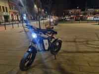
Nice bike btw, you're braver than me cycling 15 miles in current uk temperatures...
 
Thank you - Yeah it was built from the ground upwards it's got horns indicators intermittent beepers when you chose to turn left or right. 12v battery I made running GPS and all my other bits. Took me a fair bit of time to get it where it is.

Yes I have to admit I couldn't feel my nose for a few hours when I got in this afternoon :)

Will probably keep this one to one side as a backup.

I've got a 18fet 60A peak KT coming tomorrow double the torque it's rated 48-72v this one as eventually I'll be building a molicel P42 72v pack so will cover all my bases.

So to finalise things a bit for anyone who may read this down the line, was the LCD faulty as it wasn't putting power back into vIN on the controller ?
 
So to finalise things a bit for anyone who may read this down the line, was the LCD faulty as it wasn't putting power back into vIN on the controller ?

Presuming the display is KT compatible and you give a long press (about 3 secs) on the power button, it should then feed battery voltage back down the Vin line to start up the controller. If that's not happening it's probably blown the fet in the display that does this switching.

Did this display ever work on your setup?
 
Yeah it worked great. It's the KT LCD 3 one with the outside temperature.

It did exactly the same on the previous KT LCD 5 I had. This is why I've ended up with so many of them as initially I thought it was a fault in the controller.

I'm thinking it's something to do with the shunt mod I've done on them, looking back the issue occurs relatively a short time after I did this.

Could the FET in the LCD be changed then maybe ?
 
Wow great find !

Gutted that the schematic & resistor values they changed are no longer available to see as with them I'd of changed it to work upto 20S battery which is my next project :(

The FET is a PNP A1013 good for 160v and 1A of current. I'm thinking the shunt mod has put too much current through the FET and blown it.

Could I just change the FET to a higher current rating as I won't be going more than 58.8v on this display so don't need to start changing all resistor values I don't think ?
 
Could I just change the FET to a higher current rating as I won't be going more than 58.8v on this display so don't need to start changing all resistor values I don't think ?

At this point you know as much as me tbh, I've never been inside an lcd3 so can't offer any more.

Just bear in mind that I was wrong about it being a fet, A1013 looks to be a pnp power transistor, so make sure you use the correct type of device.
 
Just couple of observation from few KT OSF conversions so far:
1. the battery current reading calibration is a must. Some controllers need current calibration 95 some 88 the 12FET was 57. having imprecise calibration we risk unstable controller work and/or risk of blowing FETs
2. Motor angle tuning is quite effective, sample AKM100 motor was using 77Watt with no load in the air while 44Watt after fine tuning.
3. With 12FET (and bigger i suppose ) the controller may introduce radio interference on power line of torque sensor that leads to torque or PAS signal loss. The solution is shielding the TQ sensor cable and/or adding filter between controller and sensor.
 
Wondering if I can do the following and it would work.

I've built a 72v battery.

I have a 48v KT controller that's spare and lying around; Would it be safe to change the FETS, caps & increase the big resistor before LM317T to get the controller to work at 72v (84v @ full charge) obviously all done safely :)

Thank you :)
 
It may work; most likely you'd need to test it to be sure.

Might not be a problem, but the other part that must deal with battery voltage is the LVC sense circuit; there's likely a resistive voltage divider on it's input that then probably goes to either an op-amp or comparator and then to the MCU. If the new voltage is high enough and the resistive divider is setup the right way, it could allow more voltage into the LVC circuit than it can handle, and cause a failure (hopefully just of the buffer part, not the MCU).

Edit: maybe this is useful
https://endless-sphere.com/forums/viewtopic.php?f=2&t=115103
 
szkuba said:
Just struggling with getting PAS working properly. Any other ideas than trying different "PAS threshold"?

This CPU version seemed to not fully accept the code programming every time. So had to program it two times with same code to make sure it get it there.
IMG20221205193320.jpg
Then what it actually was i think the wrong motor specific angle. So i set 255 and it seemed work well but no in cases where the you pushed pedals really hard. Is seemed the setpoint was to "aggresive" and the controller was cutting to zero current. When i did come back to angle 237 it was all ok again..
 
szkuba said:
szkuba said:
Just struggling with getting PAS working properly. Any other ideas than trying different "PAS threshold"?

This CPU version seemed to not fully accept the code programming every time. So had to program it two times with same code to make sure it get it there.
IMG20221205193320.jpg
Then what it actually was i think the wrong motor specific angle. So i set 255 and it seemed work well but no in cases where the you pushed pedals really hard. Is seemed the setpoint was to "aggresive" and the controller was cutting to zero current. When i did come back to angle 237 it was all ok again..

hi, i also have the same problem. Total current is not zero at zero throttle. Because of this, when coasting, the controller writes (target = -0.1, current = 0.1), then I looked that the calibration comes out of calib_a (the value is configured), calib_b (the value is set by startup). looking into the source code (adc.c at 79 line) we see the code ui16_current_cal_b -= 1; for some reason it seems to me that if you remove it then the current will be 0, but I have not done it yet. I also note that the firmware for 3.9.0 sdcc is normally compiled in the root folder (win10).https://radikal.host/i/Jt99a4 https://radikal.host/i/Jt9By1

Regards
 
Actually the expression "-=" means it is substarcting this defined number from the value that is actually kept in the menory. My personal experience is that calibration of the current with external meter is really important and can improve stability. Also the PID values should be kept default.
Sid you run your tests with throttle or TQ sensor?
 
szkuba said:
Actually the expression "-=" means it is substarcting this defined number from the value that is actually kept in the menory. My personal experience is that calibration of the current with external meter is really important and can improve stability. Also the PID values should be kept default.
Sid you run your tests with throttle or TQ sensor?
I took a ride, tried different settings of everything and you can’t say. I settled on this option in the adc.c file and changed the line to a direct indication of the quiescent current for my controller: ui16_current_cal_b = 317;
. And I turned on PWMauto off, made a constant 2.5, set the motor angle to 239 based on the lowest current at max speed, it was 238. Now the current current at rest shows (317/-0.1), target (317/-0.1). sometimes the motor start ride little, but it's the little things the main thing he does not slow down as it seems to me.
Of course, this is not an ideal option, ideal, as I think, for pwm to turn off when the gas is turned off, but here in the chat there was a message that you can’t turn on pwm at speed, you need some kind of synchronization ... I’ll leave it like that.
https://radikal.host/i/JjkCcX https://radikal.host/i/JjkqYv
 
Hello everyone. I have a 50A KT SineWave controller running on my geared hub motor ebike and I am considering installing the open source firmware for a few reasons:
- Potential higher efficiency?
- Pass motor temperature sensor data to LCD8H display
- Maybe field weakening for some extra speed as I'm running 48v
If someone is able to help with some of my questions that'd be great:
- Is there a possibility to backup the stock firmware and roll back?
- By going through the threads I think LCD8H is supported by the OSF, but can someone confirm?
- Did anyone do a quick efficiency test with stock vs open source firmware (this might be subjective to hardware and settings, but still)?
- Did anyone find a way of passing motor temperature data with the stock firmware ? (aside from the arduino route) I did see some discussions on using the X4 input for that purpose.
Thanks in advance.
1678187267977.png
 
Any efficiency change from the OSFW vs OEMFW is likely to be very tiny, if there is one at all.

Efficiency of any particular set of controller hardware isn't likely to change much with different software running it, except that using field weakening will always lower your efficiency (wasting extra power to get higher speed, plus the extra power required to overcome air resistance at the higher speed).

Motor hardware may make more of an efficiency difference, for instance:
--thinner laminations
--winding optimized for the speeds and currents of this system

What is your efficiency goal, under what riding conditions and riding style, with what hardware / rider / etc?
Thanks for the reply. The goal would be to be at least as efficient as my stock 28a controller but that is unlikely as using the full 50a is very addictive.
The efficiency question was more in the lines of having osfw and fine tuning motor specifc angle vs just oemfw.

I weigh 68 kg and ride mostly full throttle using a chinese geared hub motor likely 500...750w using a 48v 25.8ah battery
 

Attachments

  • 20230304_205605.jpg
    20230304_205605.jpg
    3.7 MB · Views: 12
Thanks for the reply. The goal would be to be at least as efficient as my stock 28a controller but that is unlikely as using the full 50a is very addictive.
Well, that's not really an efficiency thing, so much as a power-usage / conservation thing, and that is up to the rider to manage (or else limit the power usage so it cannot exceed the original limit). :)

To consider efficiency differences, you'd need to use the same conditions and usage scenario--if the conditions or usage are different, you can't really compare system efficiencies.


The efficiency question was more in the lines of having osfw and fine tuning motor specifc angle vs just oemfw.

I weigh 68 kg and ride mostly full throttle using a chinese geared hub motor likely 500...750w using a 48v 25.8ah battery
There might be some difference if the controller can be tuned to "match" the motor closely, and the original didn't drive it very well, but I wouldnt' expect it to be very much. Probably more difference if it's used at high load conditions (high phase currents) a lot, vs occasional high loading and mostly low.
 
Hi guys,

Wonder if any of you KT controller gurus can help me out !!

I have a 45a KT SVPRK-SLS02G controller.

I'm getting throttle 01 abnormality error. I fix a lot of KT controllers for customers and haven't come across this issue before.

Known working throttle has been tested.
Re flowed 5V throttle, signal and ground where it meets the PCB.
I've changed the CPU chip from again a known food working 45a controller.
I'm getting 4.85v when the throttle is active. All hall sensors good etc.
Both adjust voltage regulators are good.
All fets are good no shorts; charging and dog charging correct values etc.

The throttle works for a bit then just stops and throws the error 01.

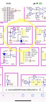
Im thinking it's something to do with the throttle circuitary. I've post the schematic about the throttle circuitary. Anything on it I should try changing or testing ?

Thank you in advance.

Nathan
 

Attachments

  • 42B4B144-F29F-48C6-8D0A-005B62874E64.jpeg
    42B4B144-F29F-48C6-8D0A-005B62874E64.jpeg
    1.2 MB · Views: 17
Managed to fix it - it was 1N4148 zener diode on the throttle schematic above. Was reading 1.3oHms when it should be 0.51kOhms. Swapped out for a good zener diode and throttle & controller works as should now.
 
Hi everyone!
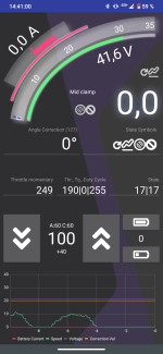
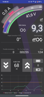
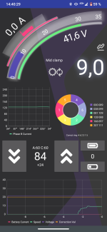
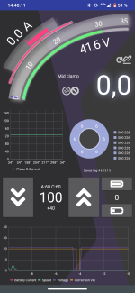
I've just flashed the firmware onto my controller and I'm having this strange problem where, I got everything hooked up (PAS, Hall sensors, Phase) but the when I turn the pedals and my PAS sensor starts register movement. The motor just doesn't do anything and spins with the pedals. While connected through the BlueOsec app I see no current flow while pedaling, even if the controller seems to get the signal. The hall sensors are in the correct sequence (4, 6, 2, 3, 1, 5) but the Phase B Current diagram remains as a straight line, is that how it's supposed to be? Also, when I spin the motor fast enough (no matter the assist level) at some point it starts to break and BlueOsec shows negative current (-0.3 A - -1.3 A) and the Phase B Current diagram shows for a second a small wave.

While operating BlueOsec shows following control states
While spinning: (1 | 34)
While still: (1 | 17)

I have the following configuration:
9FET KT36/48SVPRM - Rated current 12A (25+-A Max current)
STM8S105C6T6
ACS711 as current sensor
3PEAK TP104 as operational amplifier (may not be compatible?)


Does anybody have any clue to what's going on?
 
Last edited:
So is the motor working on the throttle?
I'm living in a country where e-bikes with throttle isn't legal, and so I don't use any. Instead I have a pas sensor installed. But no, I've tried to turn the sensor individually and with no luck. The motor remains still but BlueOsec does seem to register pas activity.

Edit:
I got my hands on a throttle and after plugging it in and testing it with my setup nothing changed. BlueOsec does see throttle activity but there's no movement on the motor.
 
Last edited:
Tried both with throttle and pas.
 

Attachments

  • Screenshot_20230415-144100.png
    Screenshot_20230415-144100.png
    402.5 KB · Views: 14
  • Screenshot_20230415-144044.png
    Screenshot_20230415-144044.png
    414.5 KB · Views: 14
  • Screenshot_20230415-144030.png
    Screenshot_20230415-144030.png
    418.2 KB · Views: 12
  • Screenshot_20230415-144012.png
    Screenshot_20230415-144012.png
    404.6 KB · Views: 14
Back
Top